Die cutting machine

A die-cutting machine and servo motor technology, applied in the direction of object supply, pile separation, thin material processing, etc., can solve the problem that overlapping paper feeding cannot be realized, and achieve the effect of accurate positioning and simple and convenient operation

Active Publication Date: 2015-03-25
唐山市隆翔印刷机械有限公司
View PDF7 Cites 4 Cited by
  • Summary
  • Abstract
  • Description
  • Claims
  • Application Information

AI Technical Summary

Problems solved by technology

[0002]In the existing traditional technology, most of the paper feeding and conveying of the die-cutting machine adopt mechanical transmission, and the paper feeding method is fish scale overlapping paper feeding. For thin corrugated paper and white board Paper can be realized, but for thick corrugated paper, overlapping paper feeding cannot be realized

Method used


Image

  • Die cutting machine
  • Die cutting machine
  • Die cutting machine

Examples


Embodiment Construction

[0026] The present invention is described in detail below in conjunction with accompanying drawing and embodiment:

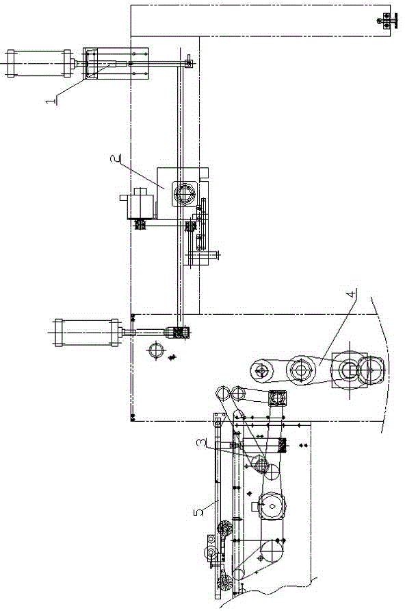
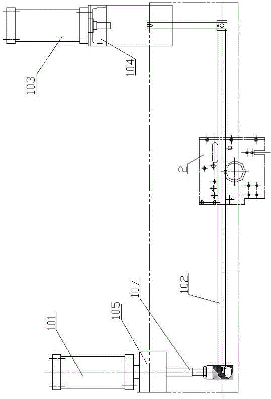
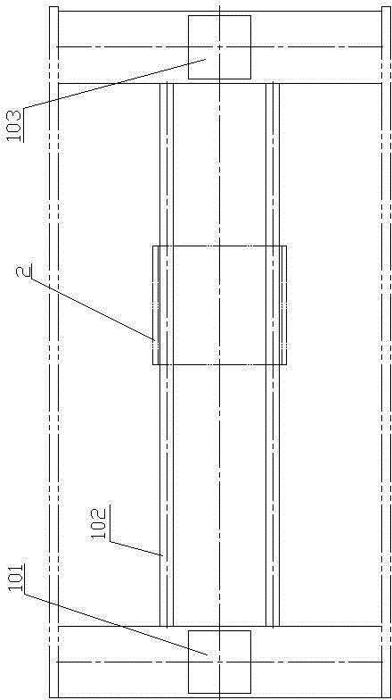
[0027] A die-cutting machine, see attached figure 1 to attach Figure 12 , in the figure: lifting mechanism 1, feeder transmission mechanism 2, paper feeding belt transmission mechanism 3, paper feeding cam transmission mechanism 4, paper feeding frame mechanism 5.

[0028] In the lifting mechanism 1: cylinder 101, front and rear moving guide rail 102, cylinder 103, cylinder 101, cylinder 103, support 104, support 105, connecting rod 106, connecting rod 107.

[0029] In Feida transmission mechanism 2: servo motor 201, driving synchronous pulley 202, synchronous belt 203, driven synchronous pulley 204, driving gear 205, driven gear 206, screw shaft 207, screw nut 208, mounting plate 209 , Paper delivery rod fixing block 210, paper delivery rod 211, main shaft servo motor 212, servo reducer 213, linear guide rail seat 214, linear guide rail 215.

[0030] In the...


PUM


Abstract

The invention relates to a printing machine, in particular to a die cutting machine. The die cutting machine comprises a lifting mechanism, a transmission mechanism, a paper conveying belt transmission mechanism, a paper conveying cam transmission mechanism and a paper conveying frame mechanism. A cylinder is adopted in the lifting mechanism to be connected with a guide rail moving forwards and backwards. A paper transfer rod is arranged on paper transfer rod fixing blocks in the transmission mechanism and provided with paper transfer suction nozzles. A driving patterned roller in a servo motor in the paper conveying belt transmission mechanism is arranged below a paper passing wheel in the paper conveying frame mechanism. A spot roller is arranged on a seventh chain wheel in the paper conveying belt transmission mechanism. A paper feeding roller and the spot roller are in a vertically corresponding state. A cylinder is arranged below a rack beam in the paper conveying frame mechanism. A driven gear and a driving gear are arranged on the rack beam. Compared with the prior art, the die cutting machine is more suitable for conveying corrugated paper in place accurately; gear and rack structural design is adopted in the paper conveying frame mechanism, adjustment can be conducted at will according to the size of the paper, and operation is easy and convenient.

Description

technical field [0001] The invention relates to a printing machine, especially a die-cutting machine. Background technique [0002] In the existing traditional technology, most of the paper feeding and conveying of the die-cutting machine adopt mechanical transmission, and the paper feeding method is fish-scale overlapping paper feeding, which can be realized for thin corrugated paper and white board paper, but not for thick corrugated paper. Overlap the paper. Contents of the invention [0003] The purpose of the present invention is to provide a die-cutting machine that can realize sheet feeding. [0004] The present invention adopts following technical scheme: [0005] A die-cutting machine, comprising a lifting mechanism (1), a transmission mechanism (2), a paper feeding belt driving mechanism (3), a paper feeding cam driving mechanism (4), a paper feeding frame mechanism (5); the lifting mechanism (1) The cylinder is connected with the front and rear moving guide r...

Claims


Application Information

Patent Timeline
Patent Type & Authority Applications(China)
IPC IPC(8): B65H5/02B65H79/00
Inventor 王建斌臧桂成
Owner 唐山市隆翔印刷机械有限公司
Why Eureka
Try Eureka