Storage shelf structure

A technology for storage racks and racks, which is applied in thin material processing, coiling strips, transportation and packaging, etc. It can solve the problems of large space occupied by storage racks, high cost of storage racks, and deformation of material belts. Achieve the effects of resource saving, convenient film penetration, and increased storage length

Inactive Publication Date: 2015-03-25
SOTECH SMARTER EQUIP CO LTD
View PDF7 Cites 10 Cited by
  • Summary
  • Abstract
  • Description
  • Claims
  • Application Information

AI Technical Summary

Problems solved by technology

For occasions that require storage racks to store more tapes, only larger volume or length storage racks can be used to meet the process requirements. The cost of the storage rack is high, and the storage rack occupies a large space, resulting in waste of resources.
[0004] In addition, during the process of conveying the material belt by the material storage rack, the subsequent processing equipment of the material belt is pulled and moved, and the material belt drives the rotating shaft on the material storage rack to rotate accordingly during the process of conveying the material belt to the subsequent processing equipment, and the material belt on the material storage rack rotates accordingly. The rotating shafts are all passive rotating shafts. The material belt drives each rotating shaft on the material storage rack during the process of conveying the material belt to the subsequent processing equipment. During the process of conveying the material belt, the material storage rack has a very large frictional resistance to the material belt. The resistance is also the tension and stretching force of the storage rack on the material belt. The material belt is stretched after being subjected to tension and tension, causing the material belt to deform. Once the material belt is deformed, it will bring great trouble to the subsequent processing. , also affects the quality of subsequent processing

Method used


Image

  • Storage shelf structure
  • Storage shelf structure

Examples


Embodiment Construction

[0018] The present invention is described in detail below in conjunction with accompanying drawing:

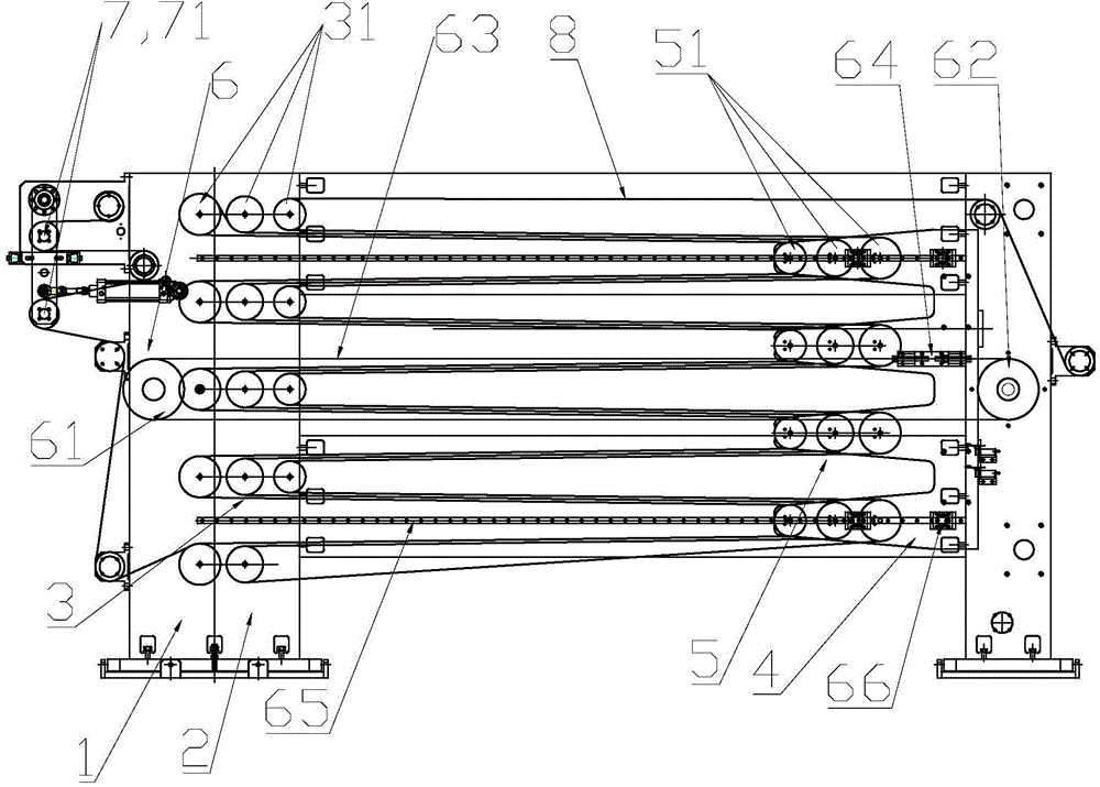
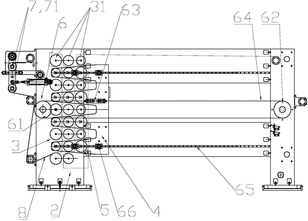
[0019] A storage rack structure, comprising a frame 1, on which a guide roller fixing frame 2 is arranged, and the guide roller fixing frame 2 is provided with multiple sets of fixed guide roller groups 3, and each group of fixed guide roller groups 3 Contains a plurality of fixed guide rollers 31, which are used to wind the material belt 8 on the fixed guide rollers 31, and the plurality of fixed guide rollers 31 are arranged horizontally from the outside to the inside according to the radius from large to small, on the frame 1 and The guide roller fixed frame 2 is relatively movable and is provided with a mobile frame 4, and the mobile frame 4 is provided with a plurality of mobile guide roller groups 5 relative to the fixed guide roller group 3, and the mobile guide roller group 5 is provided with a fixed guide roller group. The mobile guide rollers 51 with the same number ...


PUM


Abstract

The invention relates to a storage shelf structure which comprises a rack. A guide roller fixing frame is arranged on the rack and provided with multiple fixed guide roller sets. Each fixed guide roller set comprises multiple fixed guide rollers. A movable frame is arranged on the rack, moves relative to the guide roller fixing frame and is provided with multiple movable guide roller sets opposite to the fixed guide roller sets. Movable guide rollers are arranged on the movable guide roller sets. Traction devices driving the movable frame to horizontally move back and forth are arranged between the guide roller fixing frame and the movable frame. According to the storage shelf structure, a three-layer guide roller structure is adopted, the number of layers of punctured films is larger, the structure is more compact, the storage length is increased, and more materials can be stored; a double-floating-roller structure is adopted, tension change can be better buffered in the material receiving process, and the out of register influences caused by sudden change of tension in the material receiving process on printing are reduced.

Description

【Technical field】 [0001] The invention relates to equipment for a printing machine, in particular to a material storage rack structure for a printing machine. 【Background technique】 [0002] The material storage rack is an important part of the printing machine for changing rolls and docking materials. The material storage rack is used at the front end or rear end of the equipment. Specifically, the material storage rack is set at the rear end of the unwinding unit or the receiving The front-end station of the winding unit, the material storage rack is used to store a certain length of material tape. During the continuous connection process of the material tape, the material storage rack will output the material tape stored in the material storage rack, so that the subsequent lamination, bronzing , embossing, coating and other processing equipment can work without interruption. After completing the continuation of the tape, the storage rack will store a certain length of tap...

Claims


Application Information

Patent Timeline
Patent Type & Authority Applications(China)
IPC IPC(8): B65H19/14
CPCB65H19/14B65H23/26B65H2301/4165B65H2404/152
Inventor 郭景松贺志磐张幸彬郑进秦启雄
Owner SOTECH SMARTER EQUIP CO LTD
Why Eureka
Try Eureka