
Balanced lifting device

A lifting device and balancing technology, applied in the field of lifters, can solve the problems of low production cost, unbalanced lifting, and automatic balance adjustment, etc., and achieve the effect of reasonable setting and simple structure

Active Publication Date: 2015-03-25
山东佰盛能源科技有限公司
View PDF7 Cites 26 Cited by
  • Summary
  • Abstract
  • Description
  • Claims
  • Application Information

AI Technical Summary

Problems solved by technology

Existing mosquito net elevating device, or structure is too simple, as comprising early stage elevating drive, its driving wheel and line wheel combination interlocking, and driving wheel is driven by single stay rope, and each traction rope is all twisted on the winch reel, like this Although the structure is simple and the production cost is low, the traction ropes are easy to be entangled and knotted. If one of the traction ropes falls off, it will inevitably become stuck, and the cutting will continue to mess up, and it will not be able to automatically balance and adjust; It is too complicated, such as the technical scheme contained in the Chinese invention patent specification, application number 02147483.4, which includes various auxiliary mechanisms (such as multiple tractors, etc.) in addition to the driving wheel and the wire wheel, and the relationship between various auxiliary mechanisms The setting is not reasonable, resulting in
The response of each mechanism is slow, and the main hand pulls the bead chain must be pulled violently many times before each traction rope can respond in turn, and each traction rope cannot move at the same time. They are also uneven, unable to balance up and down, unable to stop half-empty, which seriously affects the use and appearance, so the existing technology needs to be improved

Method used


Image

  • Balanced lifting device
  • Balanced lifting device
  • Balanced lifting device

Examples


Embodiment Construction

[0022] The technical solutions of the present invention will be described below in conjunction with the accompanying drawings and embodiments.

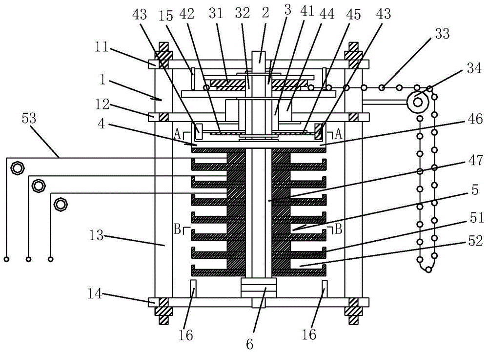
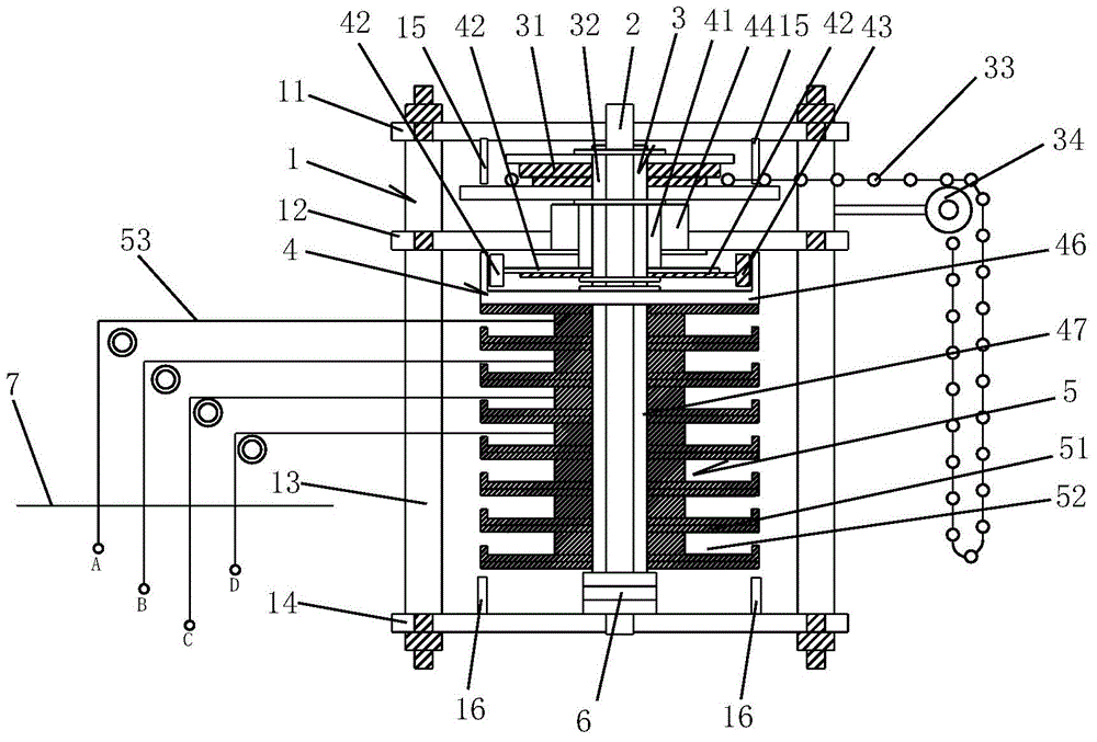
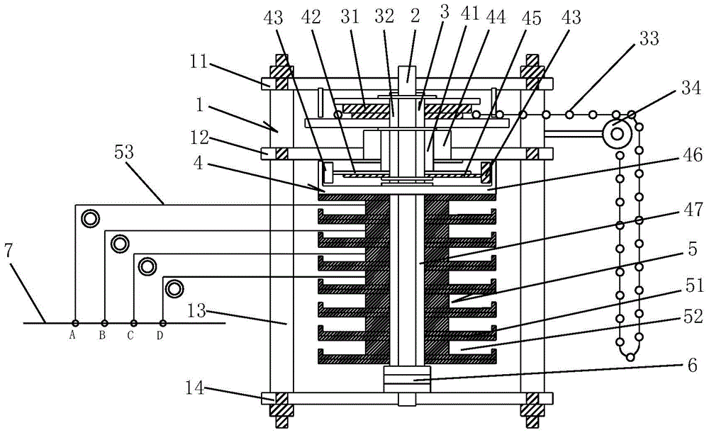
[0023] like Figure 1 to Figure 6 As shown, a kind of balance elevating device described in the present invention comprises support 1, fixed shaft 2 on the support 1, wherein said support 1 comprises upper base plate 11, lower base plate 14 and connects upper base plate 11 and lower base plate 14 A number of support sleeve rods 13, the middle part of the support sleeve rod 13 is provided with a support plate 12, the fixed shaft 2 is vertically arranged on the bracket 1, and the upper and lower ends of the fixed shaft 2 are respectively fixed on the upper base plate 11 and the lower base plate 14 superior. The above-mentioned components constitute the overall frame structure of the present invention.

[0024] The upper part of the fixed shaft 2 is provided with a driving mechanism 3. Specifically, the driving mechanism 3 includes a m...


PUM


Abstract

The invention relates to the technical field of lifters, in particular to a balanced lifting device. The balanced lifting device comprises a support and a fixed shaft fixed to the support, a driving mechanism is arranged on the upper portion of the fixed shaft, a wire wheel component is arranged on the lower portion of the fixed shaft, a clutch mechanism is arranged between the driving mechanism and the wire wheel component, the wire wheel component comprises a plurality of rope stranding discs, and an overload separation mechanism is arranged between the rope stranding discs and the clutch mechanism. The balanced lifting device is distinct in functions of all the components, reasonable in arrangement and simple and easy to mount, dismount and maintain, and ascending, descending and stopping of balanced up-and-down movement of multiple controlled hung objects or points can be realized effectively; besides, the relative level condition of the objects and points can be adjusted automatically; the lifting device is widely applicable to objects such as lifting mosquito nets, lifting drying racks, ultrahigh and ultra-wide lifting curtain rails, performance activity settings and ultra-wide banner hanging rods and the like needing ascending and descending.

Description

technical field [0001] The invention relates to the technical field of lifters, in particular to a balance lifting device, which can be widely used in lifting mosquito nets, background devices, curtain lifting guide rails, banner lifting rods, clothes drying racks and the like. Background technique [0002] The present invention is used for mosquito net lifting as main background. Existing mosquito net elevating device, or structure is too simple, as comprising early stage elevating drive, its driving wheel and line wheel combination interlocking, and driving wheel is driven by single stay rope, and each traction rope is all twisted on the winch reel, like this Although the structure is simple and the production cost is low, the traction ropes are easy to be entangled and knotted. If one of the traction ropes falls off, it will inevitably become stuck, and the cutting will continue to mess up, and it will not be able to automatically balance and adjust; It is too complicate...

Claims


Application Information

Patent Timeline
IPC IPC(8): B66D1/26B66D1/04B66D1/14A47C29/00
CPCA47C29/00B66D1/04B66D1/14B66D1/26
Inventor 冯耀明
Owner 山东佰盛能源科技有限公司
Learn More