
Outflow optimization device of pontoon type water-lifting aerator

A water pumping aeration and flow optimization technology, applied in water aeration, chemical instruments and methods, water/sludge/sewage treatment, etc., can solve the problem of increasing the amount of organic matter in water bodies, accelerating the process of eutrophication in water bodies, and increasing the number of water plants Deal with cost and other issues to achieve the effect of improving the water flow state, ensuring long-term efficient and stable operation, and avoiding fatigue damage

Inactive Publication Date: 2015-03-25
XI'AN UNIVERSITY OF ARCHITECTURE AND TECHNOLOGY
View PDF4 Cites 2 Cited by
  • Summary
  • Abstract
  • Description
  • Claims
  • Application Information

AI Technical Summary

Problems solved by technology

The large release of endogenous pollutants will cause excessive algae reproduction in high temperature seasons, and the products released by algae metabolism will increase the amount of organic matter in the water body and accelerate the eutrophication process of the water body. For lakes and reservoirs that are drinking water sources , it not only endangers the safety of drinking water, but also increases the treatment cost of the water plant

Method used


Image

  • Outflow optimization device of pontoon type water-lifting aerator
  • Outflow optimization device of pontoon type water-lifting aerator
  • Outflow optimization device of pontoon type water-lifting aerator

Examples


Embodiment Construction

[0018] The present invention will be described in further detail below in conjunction with the accompanying drawings and specific embodiments.

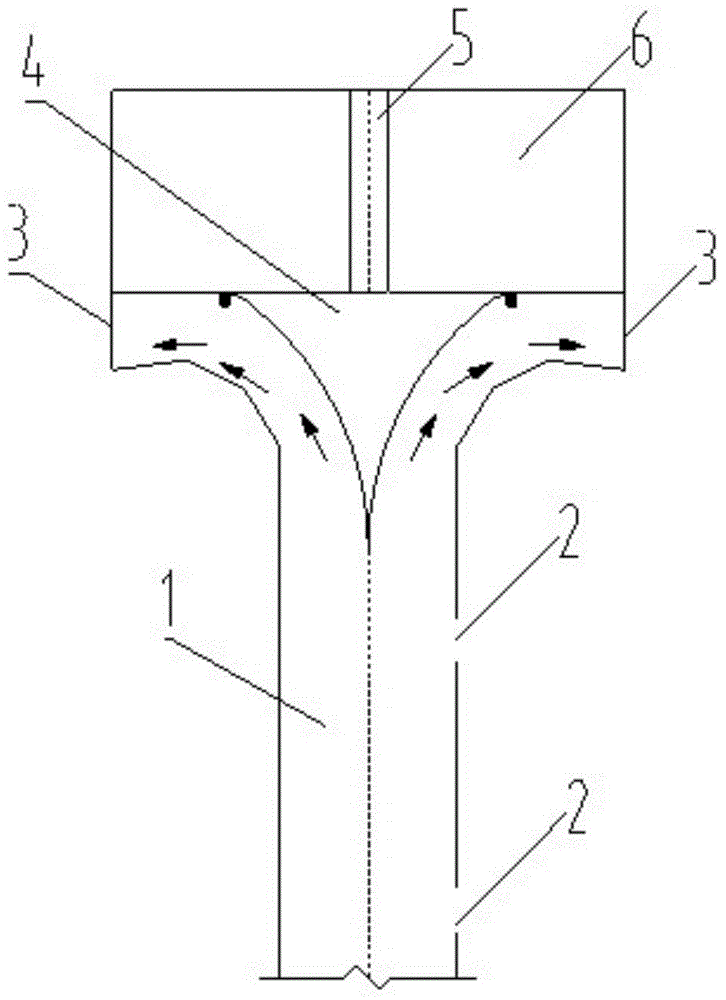
[0019] see figure 1 , a buoy-type pumping aerator outflow optimization device of the present invention, comprising a top rising cylinder 1, a middle outflow cylinder 5, a diversion cone 4 and a floating body 6; the floating body 6 is arranged on the top of the top rising cylinder 1, and the middle outflow The flow tube 5 is arranged in the center of the floating body 6, and the lower end of the middle outflow tube 5 is provided with a diversion cone 4, and the top ascending tube 1, the floating body 6 and the diversion cone 4 are formed on the top circumference of the top rising tube 1 There are several bell mouths 3 of the ascending cylinder, and several discharge holes 2 are opened on the circumference of the side wall of the ascending cylinder 1 on the top. Further, two discharge orifices 2 are provided on the circumferential dire...


PUM


Abstract

The invention discloses an outflow optimization device of a pontoon type water-lifting aerator. The outflow optimization device comprises a top ascending cylinder, a middle outflow cylinder, a diversion conical frustum and a floating body, wherein the floating body is arranged at top of the top ascending cylinder, the middle outflow cylinder is arranged at the center of the floating body, the diversion conical frustum is arranged at lower end of the middle diversion cylinder, and a plurality of bell mouths of the ascending cylinder are upwards formed in the circumferential direction of the top of the top ascending cylinder among the top ascending cylinder, the floating body and the diversion conical frustum; and a plurality of drainage holes are formed in the circumferential direction of the side wall of the top ascending cylinder. When a water flow in the ascending cylinder of the water-lifting aerator is close to an outflow device, part of the water flow firstly flows out of the side wall of the ascending cylinder, the other part of the water flow flows out in a radial manner via a channel between the diversion conical frustum and the bell mouths at the top of the ascending cylinder, and the impact force of the ascending water flow to the water-lifting aerator is reduced by about one half in comparison with an original corresponding value, so that fatigue damages to various connection parts and the floating body at the top of the water-lifting aerator are effectively avoided, energy loss when the water flow passes through the outflow device is reduced, and long-term efficient and stable operation of the water-lifting aerator is ensured.

Description

Technical field: [0001] The invention belongs to the field of water quality pollution control of lakes and reservoirs, and in particular relates to an outflow optimization device of a buoy-type water-lifting aerator, which is suitable for the transformation of the existing buoy-type water-lifting aerator and the processing of a new buoy-type water-lifting aerator, and can Make the buoy type pumping aerator more efficient and stable for the endogenous pollution and eutrophication control of the water quality of lakes and reservoirs. Background technique: [0002] The problems of endogenous pollution and eutrophication of lakes and reservoirs are widespread in the world, especially in deep-water stratified lakes and reservoirs with a water depth greater than 30 meters. Seasonal water temperature stratification is one of the main causes of endogenous pollution of lakes and reservoirs. Affected by the buoyancy resistance in the thermocline, it is difficult for the higher concent...

Claims


Application Information

Patent Timeline
IPC IPC(8): C02F7/00
CPCC02F7/00Y02W10/10
Inventor 孙昕马晓林黄廷林
Owner XI'AN UNIVERSITY OF ARCHITECTURE AND TECHNOLOGY
Learn More