
Hot sizing device and hot sizing method for thin-wall stamping part

A technology for stamping and thermal correction, which is applied in the field of thermal correction devices for thin-walled stampings, can solve problems such as warping and deformation of thin-walled stampings, and achieve the effects of avoiding warping, warping, and misalignment

Active Publication Date: 2015-03-25
AECC AVIATION POWER CO LTD
View PDF10 Cites 8 Cited by
  • Summary
  • Abstract
  • Description
  • Claims
  • Application Information

AI Technical Summary

Problems solved by technology

[0003] In order to solve the problems in the prior art, the present invention proposes a thin-walled stamping heat treatment that can solve the problem of warping and deformation of thin-walled stampings after thermal correction, thereby improving production efficiency, reducing production costs, and easy and feasible operation. Calibration device and thermal calibration method

Method used


Image

  • Hot sizing device and hot sizing method for thin-wall stamping part
  • Hot sizing device and hot sizing method for thin-wall stamping part
  • Hot sizing device and hot sizing method for thin-wall stamping part

Examples


Embodiment Construction

[0027] The present invention will be further described below in conjunction with embodiment.

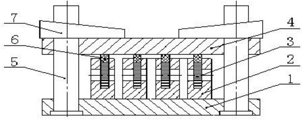
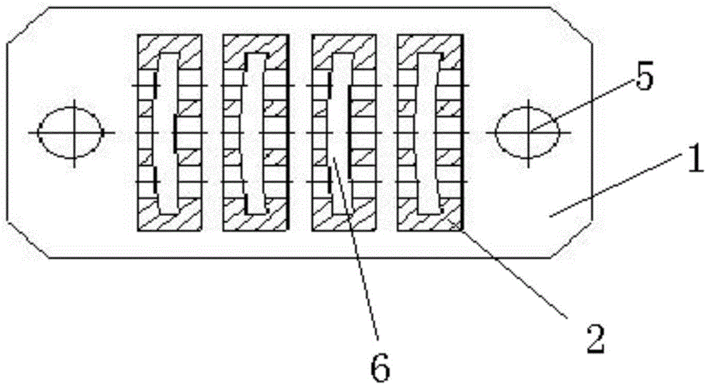
[0028] see figure 1 with figure 2 , the device of the present invention comprises a base plate 1, and positioning pins 5 fixedly arranged at both ends of the base plate 1, several loading boxes 2 are arranged on the base plate 1, and through holes for heat transfer are provided on the side walls of the loading boxes 2, and the loading boxes 2 Several thin-wall stamping parts 3 can be stacked inside, the cavity in the loading box 2 matches the size and structure of the thin-wall stamping parts 3, and the stacking height of several thin-wall stamping parts 3 is flush with the upper plane of the loading box. The upper end of the loading box 2 is provided with a pressing plate 4, the pressing plate 4 is set on the positioning pin 5, the lower end of the pressing plate 4 is provided with a pressing block 6, and the pressing block 6 is pressed on the thin-walled stamping part 3, so that ...


PUM


Abstract

The invention discloses a hot sizing device and hot sizing method for a thin-wall stamping part, and aims at solving the problems of warping and deformation of the thin-wall stamping part which is subjected to hot sizing to improve the production efficiency and reduce the production cost. The adopted technical scheme is as follows: the hot sizing device comprises a bottom plate (1) and positioning pins (5), wherein the positioning pins (5) are fixedly arranged at two ends of the bottom plate (1); the bottom plate (1) is provided with a plurality of loading boxes (2), a plurality of thin-wall stamping parts (3) can be placed in the loading boxes (2) in a stacked way, cavities inside the loading boxes (2) are matched with the thin-wall stamping parts (3) in size structure, and the stacked height of the plurality of thin-wall stamping parts (3) is aligned to the upper planes of the loading boxes (2); and the upper ends of the loading boxes (2) are provided with press plates (4), and the press plates (4) are sleeved on the positioning pins (5) so as to press the thin-wall stamping parts (3) in holes of the loading boxes (2).

Description

technical field [0001] The invention belongs to the technical field of thermal correction, and in particular relates to a thermal correction device and a thermal correction method for thin-wall stamping parts. Background technique [0002] At present, the heat correction of thin-walled stamping parts is superimposed by multiple thin-wall stamping parts, and the thin-wall stamping parts are placed on the bottom plate by manual operation. solid purpose. Because there is a huge stamping stress in the thin-walled stamping parts after stamping, it is necessary to eliminate the stamping stress, that is, heat correction treatment, and during the heat correction process, the internal stress release of the thin-wall stamping parts is irregular, coupled with the existing The tooling cannot compress the thin-walled stamping parts, so after thermal adjustment, the thin-walled stamping parts will be warped and deformed, which must be reworked, and the parts will be scrapped directly in ...

Claims


Application Information

Patent Timeline
Patent Type & Authority Applications(China)
IPC IPC(8): C21D1/30C21D9/00
Inventor 王福平陈娟娟胡建华雷晓晶陈文亮
Owner AECC AVIATION POWER CO LTD
Learn More