Soil Shoulder Blind Ditch System with Concentrated Drainage at the Side of Pavement

A technology for centralized drainage and soil shoulders, applied to waterway systems, drainage structures, water supply devices, etc., can solve problems such as unfavorable road cleaning, poor frost resistance, and incongruity, and achieve excellent driving safety and landscape effects, and stable guarantee functions Sexuality and long-acting, simple and firm structure

Active Publication Date: 2017-01-04
CCCC FIRST HIGHWAY CONSULTANTS
View PDF7 Cites 0 Cited by
  • Summary
  • Abstract
  • Description
  • Claims
  • Application Information

AI Technical Summary

Problems solved by technology

Both of the above two types of schemes have their own shortcomings. The raised waterstop scheme has road surface water, sand blocking, snow blocking, unfavorable road cleaning, poor frost resistance, small longitudinal spacing of drainage grooves, and is not suitable for small longitudinal slopes and zero longitudinal slopes. Sloping road sections and other shortcomings; the scheme of the road edge water collection tank has the disadvantages of conflicting with the position of the roadside guardrail column, small capacity, small longitudinal spacing of the gutter, poor frost resistance, uncoordinated, easily damaged, and unsafe, and some schemes are designed to increase the capacity. So as to extend the spacing of the drains, even on the premise of changing the top width of the roadbed

Method used


Image

  • Soil Shoulder Blind Ditch System with Concentrated Drainage at the Side of Pavement
  • Soil Shoulder Blind Ditch System with Concentrated Drainage at the Side of Pavement
  • Soil Shoulder Blind Ditch System with Concentrated Drainage at the Side of Pavement

Examples


Embodiment Construction

[0032] The present invention will be described in detail below in combination with specific embodiments.

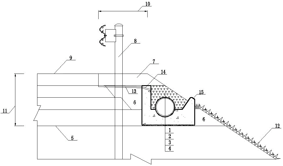
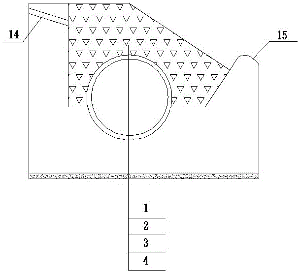
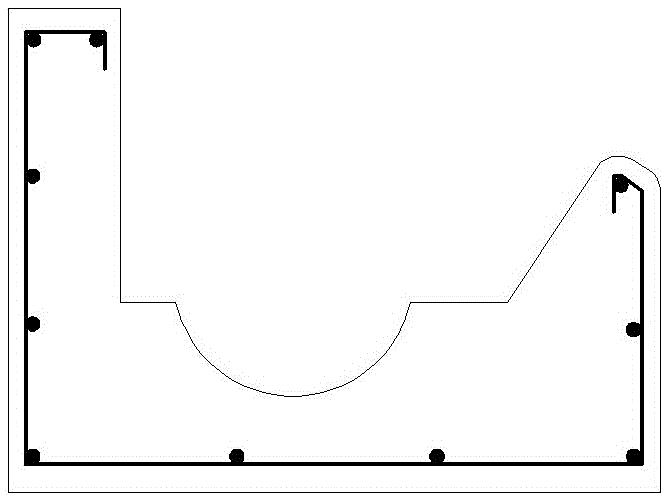
[0033] The present invention relates to an soil road shoulder blind ditch system for concentrated drainage at the edge of the road surface. A cement concrete base 3 is arranged on the top surface 5 of the road bed at the edge of the road surface, outside the roadside guardrail 8, and along the longitudinal direction of the road, using C25 cement The concrete is prefabricated and reinforced, and the length of a single section is 50cm in consideration of the convenience of transportation. A layer of cement mortar 4 is applied to the bottom surface of the cement concrete base 3, and M10 cement mortar is used to fix the base and adjust the vertical slope. The cement concrete base 3 is a groove-shaped base with a U-shaped cross section, and a longitudinal groove is reserved at the bottom of the base groove, and a semi-permeable sand-free pipe 2 is placed in the groove. The up...


PUM


Abstract

The invention relates to an earth shoulder blind ditch system for pavement edge centralized drainage. The defects such as water deposited on the pavement, sand barrier, snow barrier, inconvenience in sweeping, conflict with the guardrail position, small capacity, small longitudinal spacing of a draining tank, unsuitableness for small longitudinal slopes and zero longitudinal slope and poor anti-frost property exist in the pavement edge centralized drainage measures. According to the system disclosed by the invention, a cement concrete base is arranged on the roadbed top surface of the pavement edge along the longitudinal direction of the road; the cross section of the cement concrete base is U-shaped; a longitudinal groove is reserved in the groove bottom; a semi-transparent non-sand pipe is arranged at the groove bottom; a permeable pipe wall is arranged on the upper half part; an impermeable pipe wall is arranged on the lower half part; the upper part of the semi-transparent non-sand pipe is filled with graded broken stones to be surface of the roadbed slope. According to the system disclosed by the invention, the water on the pavement can be allowed to flow over to pavement and earth shoulder so as to permeate into the graded broken stone layer and further enters the semi-transparent non-sand pipe to flow along the longitudinal direction of the road so as to be discharged along with the draining tank, the water deposition and sand and snow barrier are avoided, the longitudinal slope adjustment capacity is high, the system can adapt to a small longitudinal slope or zero longitudinal slope road section, and frequent cutting of the side-slope protection project is avoided.

Description

technical field [0001] The invention belongs to the technical field of highway drainage engineering, and in particular relates to an earth shoulder blind ditch system for centralized drainage at the edge of the road surface. Background technique [0002] The technology of centralized drainage at the edge of the road surface is to set up water collection and drainage devices at the soil shoulders at the edge of the roadbed to intercept and discharge the rainwater on the road surface in a concentrated manner. The application of this technology can effectively eliminate the scouring hazard of road rainwater on the fill embankment slope, reduce the pressure of embankment slope protection, effectively reduce the amount of masonry for slope protection engineering, and save engineering investment. [0003] At present, this technology is widely used in domestic highways at all levels. There are two main solutions: ① Set up a raised water-retaining strip on the edge of the road surf...

Claims


Application Information

Patent Timeline
Patent Type & Authority Patents(China)
IPC IPC(8): E01C11/22E03F5/04
CPCE01C11/22E03F5/0401Y02A30/60
Inventor 吴健江兴旺倪全
Owner CCCC FIRST HIGHWAY CONSULTANTS
Why Eureka
Try Eureka