

Anti-toppling carburetor structure based on external fuel oil container
A fuel container and carburetor technology, applied in carburetors, machines/engines, engine components, etc., can solve problems such as leakage, fuel leakage, flooding, etc., and achieve high reliability, fuel saving, and high reliability
- Summary
- Abstract
- Description
- Claims
- Application Information
AI Technical Summary
Problems solved by technology
Method used
Image

Examples
Embodiment 1
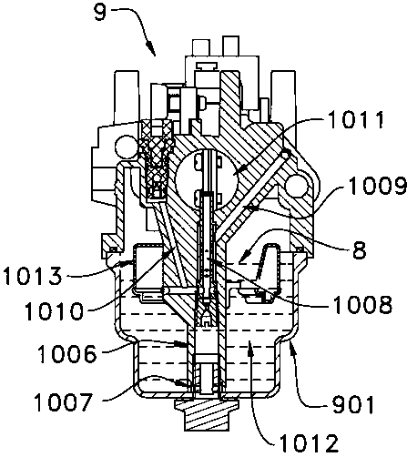
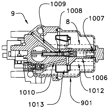
[0048] The working schematic diagram of the carburetor anti-dumping structure of the present invention is as follows: Figure 3 to Figure 4 shown.
[0049] A fuel container 1 is arranged on the left side of the carburetor 10 , the bottom of the fuel container 1 communicates with the carburetor float chamber 1012 , and the top communicates with the carburetor balance hole 1015 through the hose 6 . Such as image 3 As shown, due to the high position of the fuel container 1 , when the carburetor 10 is in a vertical state, the fuel in the float chamber 1012 will basically not enter the fuel container 1 to avoid adverse effects on the work of the carburetor 10 . When the carburetor 10 tilts to the left to a horizontal state, such as Figure 4 As shown, part of the fuel in the float chamber 1012 enters the fuel container 1 to fill it up, the remaining fuel in the float chamber 1012 is less, and the fuel level 8 is lower than the bottom opening 1007 of the upper oil pipe, so the fu...
specific Embodiment approach
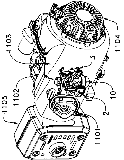
[0052] The carburetor anti-dumping structure of the present invention is that a fuel container 1 is respectively arranged on the left and right sides of the carburetor 10, and the specific implementation method is as follows:
[0053] The anti-dumping structure of the carburetor is composed of the left fuel container 2, the right fuel container 3, the sealing ring 4, the screw 5, the hose 6 and the cross 7.
[0054] The left and right sides of the oil cup 1001 of the carburetor 10 are respectively provided with a screw column 1002, and each screw column 1002 is provided with a front boss 1003 and a rear boss 1004 on both sides, and an opening is arranged in the middle of the boss. Hole 1005. A fuel container is respectively arranged on the left and right sides of the oil cup 1001 of the carburetor 10: a left fuel container 2 and a right fuel container 3, and the left fuel container 2 is composed of a left oil box 206 and an oil cover 207, The right fuel container 3 is compose...
Embodiment 2
[0066] Compared with the first embodiment, the difference of the second embodiment is that the top of the fuel container 1 communicates with the float chamber 1012 on the other side of the carburetor 10 .
[0067] Such as Figure 22 As shown, the top of the fuel container 1 arranged on the left side can communicate with the float chamber 1012 on the right side of the carburetor 10 through the hose 6 . Such as Figure 23 As shown, when the carburetor 10 tilts to the left to be horizontal, there will be a large cavity on the right side of the float chamber 1012 of the carburetor 10, allowing the air in the left fuel container 2 to enter the right side of the float chamber 1012 through the hose 6, Free flow of fuel between the fuel container 1 and the float chamber 1012 can be realized.
[0068] The specific implementation manner of embodiment two is as follows:
[0069] The anti-dumping structure of the carburetor 10 is composed of the left fuel container 2, the right fuel co...
PUM
 Abstract
Description
Claims
Application Information