
fuel system for vehicles

A fuel system and vehicle technology, which is applied in the field of vehicle fuel systems, can solve the problems of unstable emission reduction, reduced activated carbon adsorption capacity, and excessive emission, so as to avoid excessive emission, improve adsorption effect, and reduce emission.

Active Publication Date: 2017-10-10
BEIJING BORGWARD AUTOMOBILE CO LTD
View PDF5 Cites 0 Cited by
  • Summary
  • Abstract
  • Description
  • Claims
  • Application Information

AI Technical Summary

Problems solved by technology

However, if the rate of gasoline vapor flowing into the canister is increased, the capacity of the canister will be reduced
In addition, since the process of adsorbing HC in the activated carbon in the carbon canister is an exothermic process, when the temperature of the gasoline vapor flowing into the carbon canister is too high, the adsorption capacity of the activated carbon will also be greatly reduced, so the existing fuel evaporative emission control system has reduced emissions. Unstable and easily lead to the problem of excessive emission

Method used


Image

  • fuel system for vehicles
  • fuel system for vehicles

Examples


Embodiment Construction

[0030] Embodiments of the present invention are described in detail below, examples of which are shown in the drawings, wherein the same or similar reference numerals designate the same or similar elements or elements having the same or similar functions throughout. The embodiments described below by referring to the figures are exemplary and are intended to explain the present invention and should not be construed as limiting the present invention.

[0031] In the description of the present invention, it should be understood that the orientation or positional relationship indicated by the terms "inner", "outer", etc. is based on the orientation or positional relationship shown in the drawings, and is only for the convenience of describing the present invention and simplifying the description , rather than indicating or implying that the device or element referred to must have a particular orientation, be constructed and operate in a particular orientation, and thus should not ...


PUM


Abstract

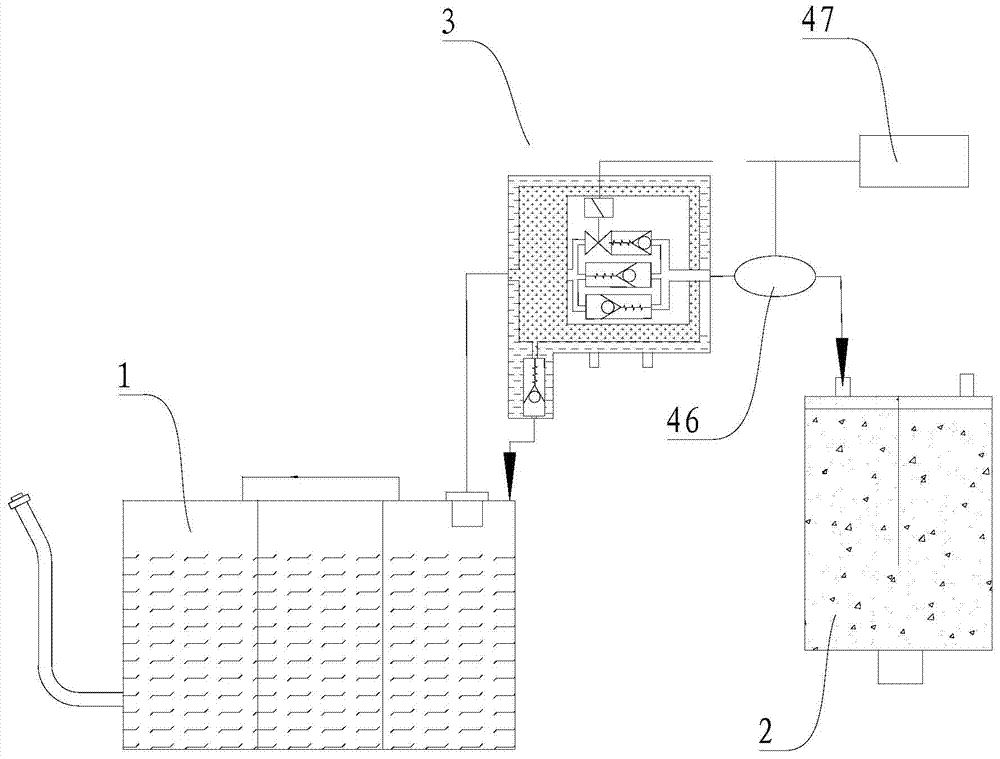
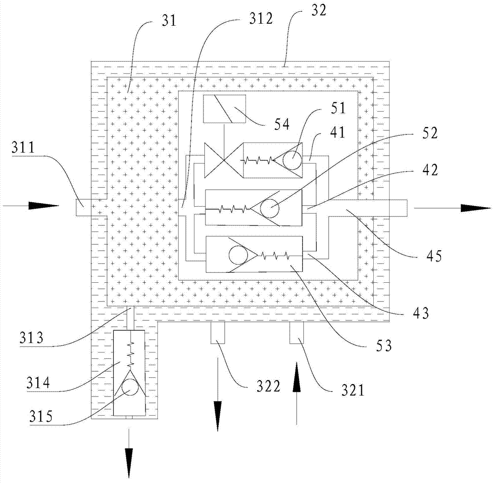
The invention discloses a fuel system for vehicles. The fuel system includes: a fuel tank pump assembly, a carbon canister assembly, and an adsorption control device arranged between the fuel tank pump assembly and the carbon canister assembly. The adsorption control device includes: a buffer chamber, the buffer chamber has an inlet and an outlet, and the buffer chamber The inlet of the tank is suitable for connecting with the fuel tank pump assembly to receive fuel vapor, the outlet of the buffer chamber is suitable for connecting with the carbon canister assembly; and a cooling device for cooling the fuel vapor in the buffer chamber. In the fuel system of the present invention, by setting an adsorption control device between the fuel tank pump assembly and the carbon canister assembly, the oil and gas flow and the temperature of the oil and gas per unit time output from the adsorption control device to the carbon canister assembly can be reduced, and then It can greatly improve the adsorption effect of the carbon canister assembly, reduce emissions, and avoid the problem of excessive emissions.

Description

technical field [0001] The invention relates to the technical field of automobile construction, in particular to a fuel system for vehicles. Background technique [0002] Existing gasoline vehicles generally use a fuel evaporative emission control system with a carbon canister as the main component. The canister is directly connected to the fuel tank. However, if you increase the rate of gasoline vapor flowing into the canister, the capacity of the canister will decrease. In addition, since the process of adsorbing HC in the activated carbon in the carbon canister is an exothermic process, when the temperature of the gasoline vapor flowing into the carbon canister is too high, the adsorption capacity of the activated carbon will also be greatly reduced, so the existing fuel evaporative emission control system has reduced emissions. Unstable and easily lead to the problem of excessive emission. Contents of the invention [0003] The present invention aims to solve one of...

Claims


Application Information

Patent Timeline
Patent Type & Authority Patents(China)
IPC IPC(8): F02M25/08
CPCF02M25/0854F02M2025/0881
Inventor 刘振山
Owner BEIJING BORGWARD AUTOMOBILE CO LTD
Learn More