Pressure type magnetic fluid wave power generation device

A technology of wave power generation and magnetic fluid, applied in the field of magnetic fluid, which can solve problems such as complex structure

Inactive Publication Date: 2015-03-25
NANJING DAWU EDUCATION TECH
View PDF3 Cites 6 Cited by
  • Summary
  • Abstract
  • Description
  • Claims
  • Application Information

AI Technical Summary

Problems solved by technology

But the above str

Method used


Image

  • Pressure type magnetic fluid wave power generation device

Examples


Embodiment Construction

[0011] Below in conjunction with accompanying drawing and specific embodiment the present invention is described in further detail:

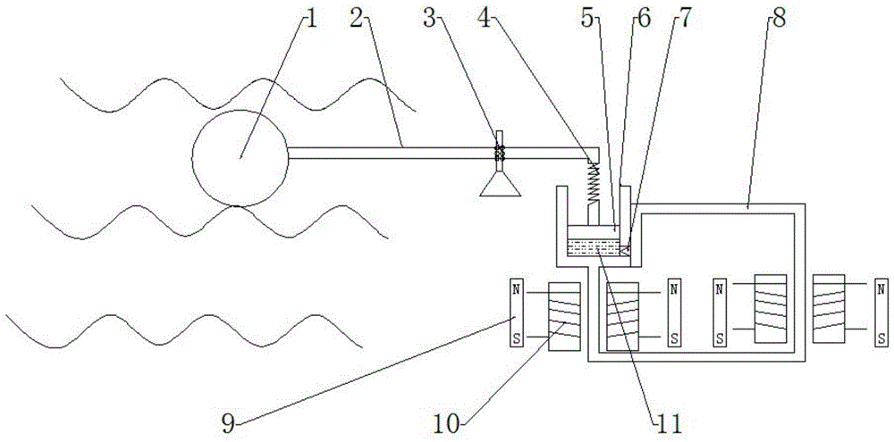
[0012] A pressure-type magnetic fluid wave power generation device of the present invention is mainly composed of the following parts: floating ball 1, linkage rod 2, rotating device 3, pressure spring 4, magnetic piston 5, cylinder body 6, single-way valve 7, magnetically permeable stiffening tube 8. Permanent magnet 9, magnetizing coil 10, magnetic fluid 11.

[0013] The working principle of the present invention is as follows: the floating ball 1 is a hollow floating body with relatively large buoyancy, which can realize relatively large ups and downs under the promotion of wave energy. The leverage principle transmits the power of the wave to the floating ball for amplified transmission. To realize the preliminary amplification of power, the spring 4 realizes the uniform and stable transmission of power and plays a stabilizing role. Magnet...


PUM


Abstract

The invention discloses a pressure type magnetic fluid wave power generation device. The device mainly comprises a floating ball (1), a linkage rod (2), a rotating device (3), a pressure spring (4), a magnetic piston (5), a cylinder (6), a one-way valve (7), a magnetic conducting rigid pipe (8), permanent magnets (9), magnetic coils (10) and a magnetic fluid (11). The working principle of the device is as follows: the magnetic piston (5), the cylinder (6), the one-way valve (7) and the magnetic conducting rigid pipe (8) form a magnetic fluid emitting and recovering process; the magnetic fluid (11) in the cylinder (6) is extruded by the magnetic piston (5); because of the conducting principle, a great initial velocity can be obtained when the magnetic fluid (11) enters the magnetic conducting rigid pipe (8) again; the magnetic fluid (11) passes through a power generation electromagnetic field formed by the permanent magnets (9) and the magnetic coils (10) with high speed; and current can be obtained at the output end of a coil to achieve the power generation purpose.

Description

technical field [0001] The invention relates to the field of magnetic fluid, in particular to a pressure-type magnetic fluid wave power generation device utilizing wave energy for power generation. Background technique [0002] Harnessing the ocean's waves to generate electricity is an important aspect of renewable energy production. The prior art has occurred the generating set that adopts the impeller machine that utilizes wave, generator to form. It includes setting openings for introducing sea waves, setting one / or multiple impellers capable of introducing two-way air flow to change the angle of moving blades and having the same steering function on multiple airflow holes, and connecting a generator. Use the up and down floating of seawater to enter the integral interval / or split independent wave chamber body to compress air or form negative pressure to supplement the air. The two-way swinging moving blades of the turbine output the torque in the same direction of rotat...

Claims


Application Information

Patent Timeline
IPC IPC(8): F03B13/14
CPCY02E10/30
Inventor 高蓉
Owner NANJING DAWU EDUCATION TECH
Why Eureka
Try Eureka