Compressor

A compressor and anechoic cavity technology, applied in the field of compressors, can solve the problems of limited muffler muffler capacity, poor muffler muffler effect, and small muffler volume, achieving small increase in design cost and processing cost, simple structure, and reduced noise volume effect

Active Publication Date: 2015-03-25
GUANGDONG MEIZHI COMPRESSOR
View PDF9 Cites 2 Cited by
  • Summary
  • Abstract
  • Description
  • Claims
  • Application Information

AI Technical Summary

Problems solved by technology

Due to structural limitations, the traditional muffler has a small amount of noise reduction, and even in some frequency bands, the noise reduction effect of the muffler is poor, resulting in a limited overall noise reduction capability of the muffler.

Method used


Image

  • Compressor
  • Compressor
  • Compressor

Examples


Embodiment 1

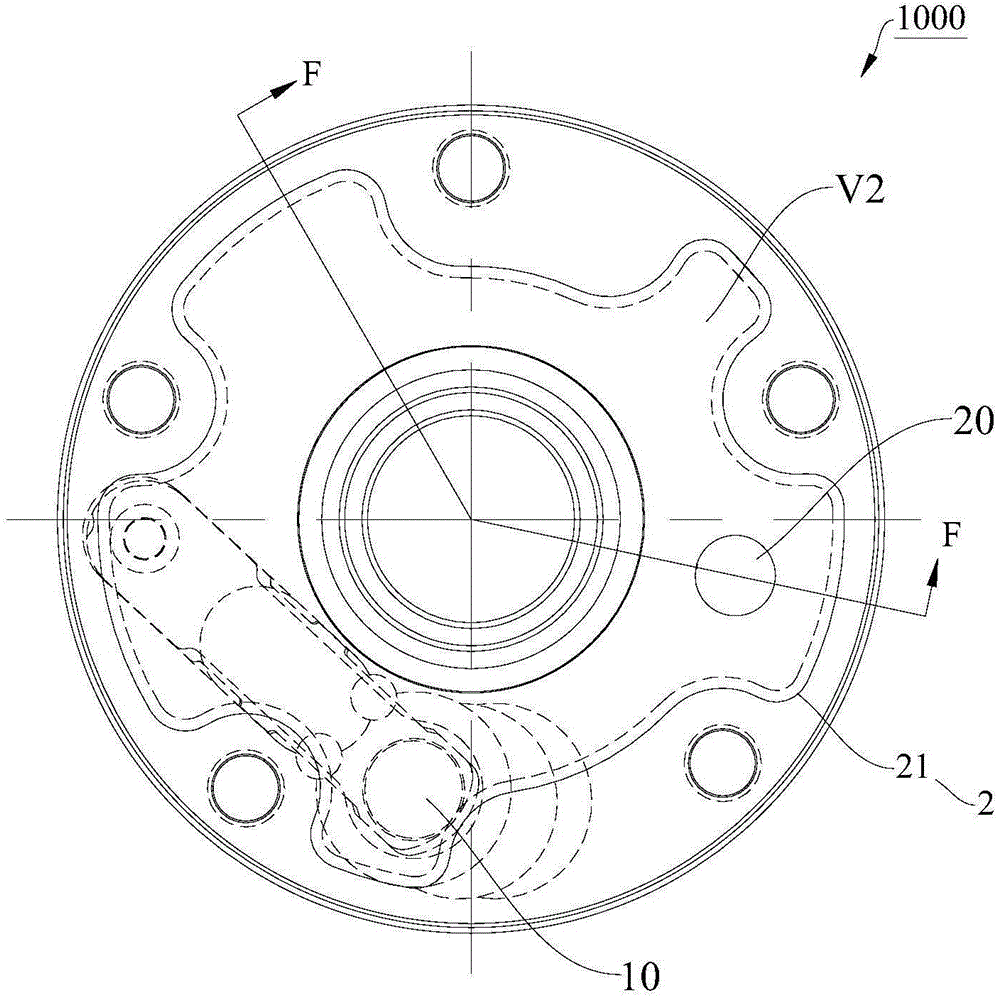
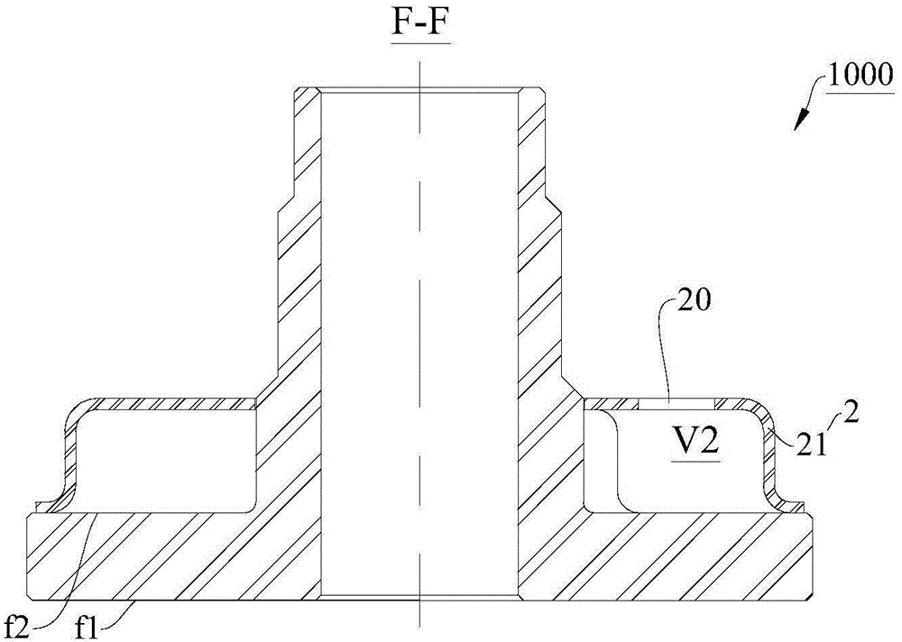
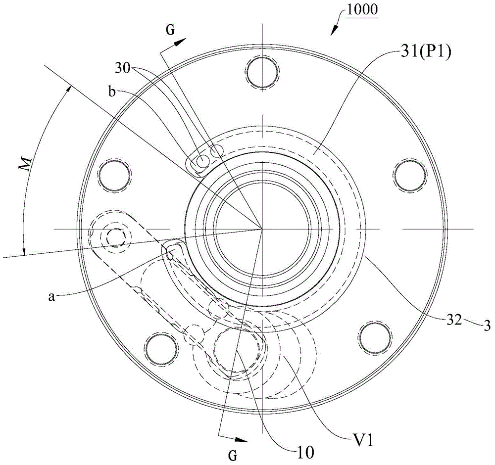
[0071] In the first embodiment, if Figure 1-Figure 6 As shown, the compressor 1000 is in the figure 1 with figure 2 The conventional structure shown adds the image 3 with Figure 4 The first sound-absorbing partition 32 shown, the combined structure is as follows Figure 5 with Image 6 shown.

[0072]Wherein, the first noise-absorbing baffle 32 is formed in an annular shape and is sheathed on the hub 12 of the bearing 1, and a part of the first silencing baffle 32 is recessed toward a direction away from the bearing 1 to form a groove 31, and the groove 31 is in contact with the bearing. The second end surface f2 of 1 cooperates to define the first sub-muffling cavity P1. The first sub-muffling chamber P1 is formed in an arc shape extending around the center of the first sound-absorbing partition 32 , and two second exhaust holes 30 are provided at the ends of the first sub-muffling chamber P1 . The first muffler 21 is arranged on the first muffler baffle 32 , and a...

Embodiment 2

[0075] In the second embodiment, if Figure 8-Figure 11 As shown, the compressor 1000 is in the Figure 8 with Figure 9 In the traditional structure shown, the first sound-absorbing partition 32 is added, and the combined structure is as follows Figure 10 with Figure 11 shown.

[0076] Wherein, the second muffler 22 is disposed on the first muffler baffle 32 , and the second muffler 22 is provided with two third exhaust holes 20 . Moreover, compared with the first muffler 21 in the first embodiment, the shape of the second muffler 22 is also changed.

[0077] Figure 14 Shown is the inventor's comparative study of compressors without the first noise-absorbing partition 32 and with the first noise-absorbing partition 32, and the curve C in the figure shows that the second muffler 22 combines the first noise-absorbing partition The transmission loss distribution diagram behind the plate 32, the D curve in the figure represents the transmission loss distribution diagram ...

Embodiment 3

[0079] In the third embodiment, the compressor 1000 is Figure 8 with Figure 9 The conventional structure shown adds the Figure 12 The second sound-absorbing partition 33 is shown.

[0080] Wherein, the second noise-absorbing partition 33 is formed in an annular shape and is sheathed on the hub 12 of the bearing 1, and a part of the second noise-absorbing partition 33 is recessed toward a direction away from the bearing 1 to form a groove 31, and the groove 31 is in contact with the bearing. The second end surface f2 of 1 cooperates to define the first sub-muffling cavity P1. The first sub-muffling chamber P1 is formed as a connected circular ring extending around the center of the second muffling partition 33 , and two second exhaust holes 30 are arranged on the second muffling partition 33 .

[0081] Figure 14 It also shows the comparative research conducted by the inventor on the compressors without the second noise-absorbing partition 33 and with the second noise-ab...


PUM


Abstract

The invention discloses a compressor. The compressor comprises a cylinder assembly, a bearing, a silencer and a silencing partition. The bearing is arranged on the end face of the cylinder assembly, a first exhaust hole is formed in the bearing, the silencer is arranged on the end face of the bearing, and a silencing cavity is defined by the silencer and the bearing. The silencing partition is arranged on the end face of the bearing, at least one part of the silencing partition is recessed in the direction away from the bearing so that a first sub silencing cavity can be defined by the silencing partition and the surface where the bearing is located, a second sub silencing cavity is defined by the silencing partition and the silencer, the first sub silencing cavity is communicated with the first exhaust hole, and a second exhaust hole for allowing the first sub silencing cavity and the second sub silencing cavity to be communicated is formed in the silencing partition. According to the compressor, the silencing partition is arranged between the bearing and the silencer, gas refrigerant exhausted into the silencer is silenced twice, and therefore the silencing amount of the compressor is increased. The compressor is simple in structure and small in increase of design cost and machining cost.

Description

technical field [0001] The invention relates to the field of compressors. Background technique [0002] The compressor is the core component of the refrigeration system, and its working characteristics determine that the compressor is also the main noise source of the refrigeration system. The compressor noise includes airflow noise, mechanical noise and motor noise. The muffler is a mechanism used to suppress the airflow noise of the compressor, and the muffler is generally installed on the bearing. Due to structural limitations, the traditional muffler has a small amount of noise reduction, and even in some frequency bands, the noise reduction effect of the muffler is poor, resulting in a limited overall noise reduction capability of the muffler. Contents of the invention [0003] The present invention aims to solve at least one of the technical problems existing in the prior art. For this reason, the present invention aims to provide a compressor whose noise reduction...

Claims


Application Information

Patent Timeline
Patent Type & Authority Applications(China)
IPC IPC(8): F04B39/00
Inventor 郝唯张诚
Owner GUANGDONG MEIZHI COMPRESSOR
Why Eureka
Try Eureka