High-power centrifugal fan with adjustable supply air rate

A centrifugal fan, high-power technology, used in mechanical equipment, machines/engines, liquid fuel engines, etc., can solve the problems of increased installation and production costs, inability to start the motor, low work efficiency, etc., to save production costs and installation. Cost, preventing failure to start, and high work efficiency

Inactive Publication Date: 2015-03-25
JIANGSU SHUANGJU FANS
View PDF4 Cites 7 Cited by
  • Summary
  • Abstract
  • Description
  • Claims
  • Application Information

AI Technical Summary

Problems solved by technology

[0002] The fan is a machine that relies on the input mechanical energy to increase the gas pressure and discharge the gas. It is a driven fluid machine. At present, the fan is widely used in various fields. The existing centrifugal fans all use a single volute Working with a single impeller, the power is relatively small and the work efficiency is low. If you need to purchase a large number of fans, the installation cost and production cost will increase significantly; at the same time, the existing fans are generally fully open, and the moment the motor starts to drive the impeller to rotate , due to the large load of the motor, using the fully open state will cause the motor to fail to start or even be damaged; in addition, after the fan is started, some occasions have relatively high requirements for wind force and need to work within a certain wind speed range, and the existing fan cannot adjust the air intake. Wind speed and wind speed, can not meet people's use requirements

Method used


Image

  • High-power centrifugal fan with adjustable supply air rate
  • High-power centrifugal fan with adjustable supply air rate
  • High-power centrifugal fan with adjustable supply air rate

Examples


Embodiment Construction

[0012] The specific content of the present invention will be described in detail below in conjunction with the accompanying drawings and specific embodiments.

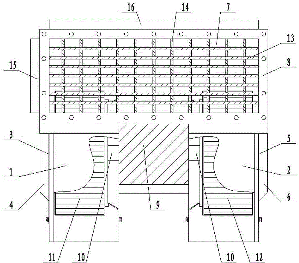
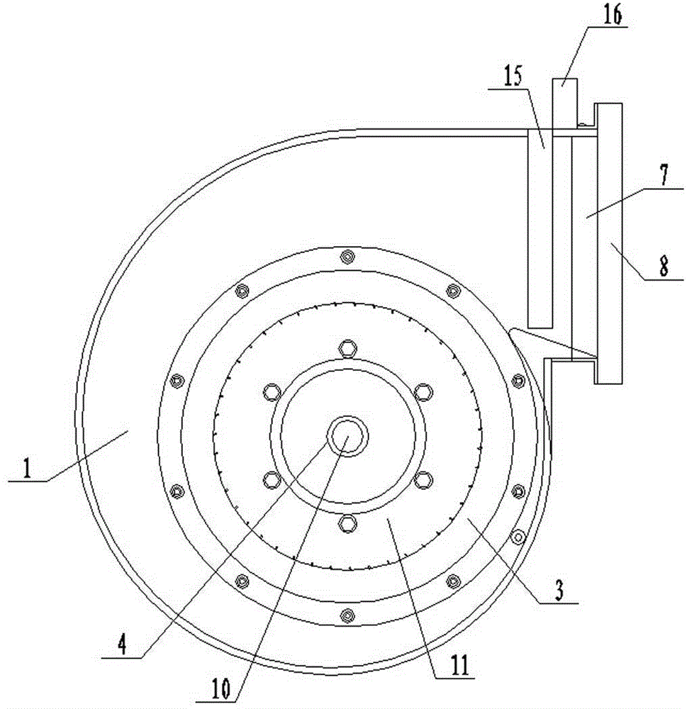
[0013] Such as figure 1 , figure 2 , image 3 , Figure 4 , Figure 5 As shown, the integrated high-power centrifugal ventilation with adjustable wind speed

[0014] machine, including: a left volute 1 and a right volute 2, a left air inlet 3 and a left motor shaft mounting bracket 4 are arranged on the left side of the left volute 1, and a The right air inlet 5 and the right motor shaft mounting bracket 6 are provided with an air outlet 7 and an air outlet fixing flange 8 on the end faces of the left volute 1 and the right volute 2, and the air outlet 7 is connected with the left air inlet at the same time. The tuyere 3 communicates with the right air inlet 5, and a double-shaft three-phase asynchronous motor 9 is arranged between the left volute 1 and the right volute 2, and one end of the motor shaft 10 of the...


PUM


Abstract

The invention discloses a high-power centrifugal fan with an adjustable supply air rate. The high-power centrifugal fan comprises a left volute and a right volute. A left air inlet and a left motor shaft installation support are arranged on the left side of the left volute. A right air inlet and a right motor shaft installation support are arranged on the right side of the right volute. A double-shaft extending three-phase asynchronous motor is arranged between the left volute and the right volute. Transverse wind blocking blades are connected with a transverse control motor arranged on one side of the air outlet. Vertical wind blocking blades are connected with a vertical control motor arranged at the upper end of the air outlet. The left air inlet and the right air inlet are connected with a square air inlet pipeline. A wind speed adjusting device is arranged on the square air inlet pipeline. The wind speed adjusting device comprises an adjusting baffle, an inserting groove matched with the adjusting baffle is formed in the square air inlet pipeline, the upper end of the adjusting baffle is connected with a piston rod of an air cylinder through an L-shaped connecting rod, and the air cylinder is fixedly arranged on the square air inlet pipeline.

Description

technical field [0001] The invention relates to a fan, in particular to a high-power centrifugal fan with adjustable air intake. Background technique [0002] The fan is a machine that relies on the input mechanical energy to increase the gas pressure and discharge the gas. It is a driven fluid machine. At present, the fan is widely used in various fields. The existing centrifugal fans all use a single volute Working with a single impeller, the power is relatively small and the work efficiency is low. If you need to purchase a large number of fans, the installation cost and production cost will increase significantly; at the same time, the existing fans are generally fully open, and the moment the motor starts to drive the impeller to rotate , due to the large load of the motor, using the fully open state will cause the motor to fail to start or even be damaged; in addition, after the fan is started, some occasions have relatively high requirements for wind force and need t...

Claims


Application Information

Patent Timeline
Patent Type & Authority Applications(China)
IPC IPC(8): F04D17/14F04D25/08
CPCF04D29/424F04D27/0246
Inventor 孙勇安孙健
Owner JIANGSU SHUANGJU FANS
Why Eureka
Try Eureka