Machine needle driving mechanism for spatial four-rod embroidery machine

A driving mechanism, embroidery machine technology, applied in the direction of embroidery machine mechanism, embroidery machine, mechanical equipment, etc., can solve the problems such as strict limitation of use scope, difficulty in replacement, and difficulty in installation of power shafts

Inactive Publication Date: 2015-03-25
ZHEJIANG SCI-TECH UNIV
View PDF5 Cites 0 Cited by
  • Summary
  • Abstract
  • Description
  • Claims
  • Application Information

AI Technical Summary

Problems solved by technology

[0002] The needle driving mechanism is one of the core components of the embroidery machine, which has high requirements on the motion characteristics. At present, the needle driving mechanism of the embroidery machine mainly adopts the horizontal arrangement of the power shaft. When the distance is small, the power shaft is difficult to install.
The cam transmission mechanism widely us

Method used


Image

  • Machine needle driving mechanism for spatial four-rod embroidery machine
  • Machine needle driving mechanism for spatial four-rod embroidery machine
  • Machine needle driving mechanism for spatial four-rod embroidery machine

Examples


Embodiment Construction

[0018] The present invention will be further described below in conjunction with accompanying drawing.

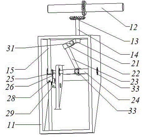
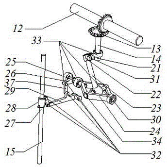
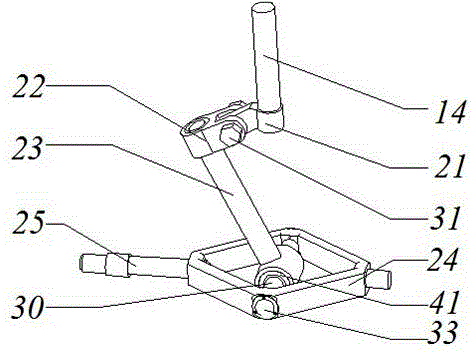
[0019] like Figure 1-5 As shown, the needle driving mechanism of the space four-bar embroidery machine of the present invention mainly includes a power input part, a casing 11, a driving mechanism, and a power output part. The power input part is mainly composed of a main shaft 12 and a pair of bevel gears 13 installed on the main shaft 12 and the driving rod 14 . The lower end of the drive rod 14 is fixed with a ring joint 21 , and the ring joint 21 and the adapter 22 are fixed by a nut screw 31 . The installation angle between the ring joint 21 and the adapter 22 can be changed arbitrarily to meet the installation requirements. After the installation is completed, the ring joint 21 and the adapter 22 must be fixed.

[0020] The driving mechanism includes a space four-bar part and a planar four-bar part, and the two parts are connected by a swing shaft 25 . The space f...


PUM


Abstract

The invention discloses a machine needle driving mechanism for a spatial four-rod embroidery machine. The mechanism mainly comprises a power input part, a box body, a driving mechanism and a power output part, wherein the power input part mainly comprises a main shaft and a pair of bevel gears mounted on the main shaft and a driving rod; the driving mechanism comprises a spatial four-rod part and a planar four-rod part which are connected through a swinging shaft. According to the machine needle driving mechanism for the spatial four-rod embroidery machine, power is input by the main shaft, transmission is carried out through the bevel gears, swinging of the swinging shaft is realized through the spatial four-rod mechanism, the power is output through the planar four-rod mechanism, and a machine needle driving block can slide up and down. The stroke and movement speed of a needle rod can be regulated by regulating the planar four-rod part according to actual situations.

Description

technical field [0001] The invention relates to the needle drive field of embroidery machines, in particular to a space four-bar embroidery machine needle drive mechanism. Background technique [0002] The needle driving mechanism is one of the core components of the embroidery machine, which has high requirements on the motion characteristics. At present, the needle driving mechanism of the existing embroidery machine mainly adopts the horizontal arrangement of the power shaft. When the distance is small, the power shaft is difficult to install. The cam transmission mechanism widely used in the market, due to the compact structure, the impact of power input is relatively large, the cam is seriously worn, it is difficult to replace and the design of the cam is difficult. In the cam needle drive mechanism, a single cam is directly connected to the needle drive slider. The movement speed and stroke of the slider cannot be adjusted, and the scope of use is strictly limited. C...

Claims


Application Information

Patent Timeline
IPC IPC(8): F16H21/54D05C11/06
CPCD05C11/06F16H21/54
Inventor 张雷贺虎苏宗帅
Owner ZHEJIANG SCI-TECH UNIV
Why Eureka
Try Eureka