Electrically-controlled tee valve and washer with same
A technology of three-way valve and washing machine, applied to other washing machines, applications, multi-way valves, etc., can solve the problems of affecting the washing effect, inconvenient control of the three-way drain valve, and no reduction in human operation, so as to achieve automation and reduce Small secondary pollution, simple structure effect
- Summary
- Abstract
- Description
- Claims
- Application Information
AI Technical Summary
Problems solved by technology
Method used
Image

Examples
Embodiment 1
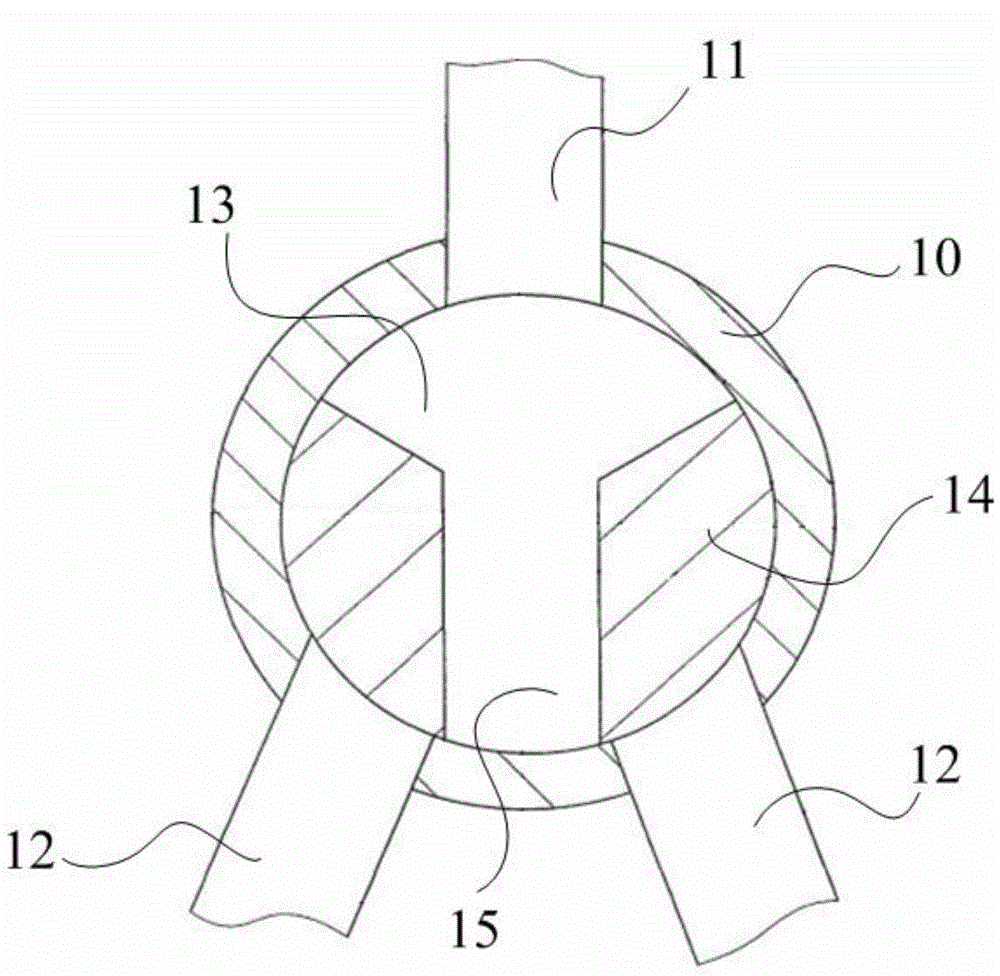
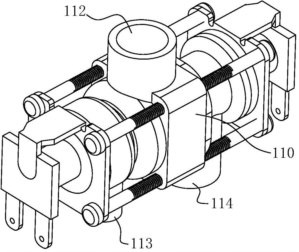
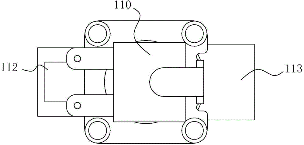
[0046] Such as Figure 2-8 As shown, in this embodiment, an electronically controlled three-way valve according to the present invention includes a cylindrical valve body 110, the valve body 110 has a cavity inside to form a valve cavity 111, and the valve body 110 A first valve port 112 is provided in the middle of the side wall, and a second valve port 113 and a third valve port 114 are respectively provided on the side wall of the valve body 110 opposite to the first valve port 112 near both ends. The first valve port 112 , the second valve port 113 and the third valve port 114 are all in communication with the valve cavity 111 .
[0047] Such as Figure 5 As shown, the valve chamber 111 is provided with a sliding shaft 115 that can slide in the valve chamber 111, and a valve core 116 is fixedly installed on the sliding shaft 115, and the valve core 116 and the sliding shaft 115 can move together to realize selective closing. The channel between the first valve port 112 a...
Embodiment 2
[0056] Such as Figures 9 to 12 As shown, the main difference between this embodiment and Embodiment 1 is that, in this embodiment, only an electromagnet 217 is set at one end of the valve chamber 211 inside the valve body 210 as the control end of the electric control three-way valve, and a function is set at the other end. The return spring 218 whose force is opposite to the direction of the force of the electromagnet 217, wherein the elastic force of the return spring 218 is smaller than the attraction force to the sliding shaft 215 when the electromagnet 217 is working.
[0057] In this embodiment, the communication between the first valve port 212 and the third valve port 214 is realized by electrifying the electromagnet 217 . When the electromagnet 217 is de-energized, the return spring 218 acts to realize the communication between the first valve port 212 and the second valve port 213 .
[0058] Such as Figure 11 , 12 As shown, the return spring 218 is sleeved on th...
Embodiment 3
[0062] Such as Figure 13 , 14 As shown, a washing machine is introduced in this embodiment, and the electric control three-way valve 312 described in Embodiment 1 or Embodiment 2 is provided at the outlet 316 of the drain pump 311 at the bottom of the washing machine housing 310, and the electric control three-way The first valve port 313 of the valve 312 is used as the water inlet to connect to the water outlet 316 of the drainage pump, the second valve port 314 of the electronically controlled three-way valve 312 is connected to the circulating water pipe 317, and the third valve port 315 of the electronically controlled three-way valve 312 is connected to the Drain pipe 318 for discharging washing sewage.
[0063] Preferably, a filter device 320 is provided at the connection between the second valve port 314 and the circulating water pipe 317, through which the filter device 320 can filter out part of the dirt washed from the clothes in the washing water, so that the wash...
PUM
 Abstract
Description
Claims
Application Information
PatSnap Eureka turns technology decisions into work you can execute. Powered by our Innovation Knowledge Graph, it runs expert workflows across engineering, life sciences, materials and intellectual property. Get your review-ready output in minutes.


