High-insulativity LED tube lamp structure

An LED tube light, insulating technology, applied in the parts of lighting devices, lighting devices, light sources, etc., can solve the problems of time-consuming threading process, dislocation of lead wires, affecting work efficiency, etc., and achieve the effect of convenient connection and assembly.

Inactive Publication Date: 2015-03-25
XIAN XINWEI INFORMATION TECH
View PDF0 Cites 0 Cited by
  • Summary
  • Abstract
  • Description
  • Claims
  • Application Information

AI Technical Summary

Problems solved by technology

[0003] It can be seen from the above structure that at least four wires pass through the semi-cylinder, and the power supply cannot be effectively fixed. The threading process is ti

Method used


Image

  • High-insulativity LED tube lamp structure
  • High-insulativity LED tube lamp structure
  • High-insulativity LED tube lamp structure

Examples


Embodiment 1

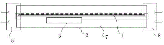
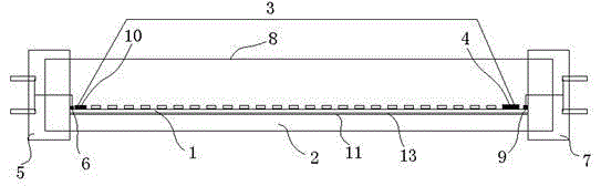
[0017] Such as figure 2 As shown, a LED tube light structure with good insulation includes a lamp board 1, a lamp board frame 2 and a power supply 3, wherein the rectifier IC 10 in the power supply 3 is at one end of the lamp board 1, and the constant current circuit 4 in the power supply is at the end of the lamp board. At the other end of the board 1, the lamp beads 12 are between the rectifier IC10 and the constant current circuit 4; The non-welding surface 13 of the board 1 is connected to the plane surface 11 of the lamp board frame 2 by heat conduction; an AC input end of the rectifier IC and the adjacent first lamp holder 5 (the left end in the figure) have an AC first welding wire plate 6, and an AC second A wire reel 6 is electrically connected to the terminal of the first lamp holder 5; the other AC input terminal of the rectifier IC is routed through the lamp board to the second AC soldering terminal near the second lamp holder 8 (the right end in the figure) at th...

Embodiment 2

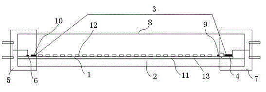
[0019] Such as image 3 As shown, a LED tube light structure with good insulation includes a lamp board 1, a lamp board frame 2 and a power supply 3, wherein the rectifier IC 10 in the power supply 3 is at one end of the lamp board 1, and the constant current circuit 4 in the power supply is at the end of the lamp board. At the other end of the board 1, the lamp beads 12 are between the rectifier IC10 and the constant current circuit 4; The non-welding surface 13 of the board 1 is connected to the plane surface 11 of the lamp board frame 2 by heat conduction; an AC input end of the rectifier IC and the adjacent first lamp holder 5 (the left end in the figure) have an AC first welding wire plate 6, and an AC second A wire reel 6 is electrically connected to the terminal of the first lamp holder 5; the other AC input terminal of the rectifier IC is routed through the lamp board to the second AC soldering terminal near the second lamp holder 8 (the right end in the figure) at the...


PUM


Abstract

The invention discloses a high-insulativity LED tube lamp structure which comprises a lamp plate, a lamp plate frame and a power source. A rectifier IC in the power source is positioned at one end of the lamp plate, a constant-current circuit in the power source is positioned at the other end of the lamp plate, lamp beads are positioned between the rectifier IC and the constant-current circuit, the rectifier IC and the lamp beads are welded on the lamp plate and distributed along the length direction of the lamp plate frame, a non-welding face of the lamp plate and a plane of the lamp plate frame are in heat-conducting connection, an alternating-current first welding wire disc is arranged between an alternating-current input end of the rectifier IC and a first lamp holder close to the alternating-current input end, the alternating-current first welding wire disc is electrically connected with a wiring end of the first lamp holder, another alternating-current input end of the rectifier IC routes onto an alternating-current second welding wire disc, close to a second lamp holder, at the other end of the lamp plate, the alternating-current second welding wire disc is electrically connected with a wiring end of the second lamp holder, a positive output end of the rectifier IC is electrically connected with one end of the lamp plate LED lamp bead, the other end of each lamp plate LED lamp bead is electrically connected with a positive input end of the constant-current circuit, and a negative output end of the constant-current circuit is electrically connected with a negative output end of the rectifier IC. The high-insulativity LED tube lamp structure is high in structuredness and reliability.

Description

technical field [0001] The invention relates to an LED tube lamp, in particular to an LED tube lamp structure with good insulation. Background technique [0002] Such as figure 1 As shown, the structure of the existing LED tube lamp is given; including the lamp board and the lamp board frame, the lamp board frame is a semi-cylindrical aluminum alloy frame, the semi-circular plane fixes the lamp board, and the semi-cylindrical cavity fixes the power supply; the power supply includes at least four lines, Two of them are connected to 220v power supply as the input terminal of AC power supply, and two of them are used as DC voltage terminals to supply the DC voltage of the LED light board. When installing, the two wires of the power supply in the semi-cylindrical shape are drawn from the left end of the semi-cylindrical cylinder to the left end, and the other two wires are drawn from the right end of the semi-cylindrical cylinder to the right end. One of the two wires at the ri...

Claims


Application Information

Patent Timeline
IPC IPC(8): F21S2/00F21V23/06F21Y101/02
CPCF21S2/00F21V23/06
Inventor 刘珉恺
Owner XIAN XINWEI INFORMATION TECH
Why Eureka
Try Eureka