
Process layout method for conventional hypersonic speed wind tunnel

A hypersonic, process layout technology, applied in the field of aerodynamics, can solve the problems of high dynamic sealing requirements, limit the wind tunnel simulation ability, increase the structural complexity of the test section, etc., achieve the effect of reliable vacuum sealing and improve the test simulation ability

Inactive Publication Date: 2015-03-25
BEIJING AEROSPACE YISEN WIND TUNNEL ENG TECH
View PDF5 Cites 32 Cited by
  • Summary
  • Abstract
  • Description
  • Claims
  • Application Information

AI Technical Summary

Problems solved by technology

The simulation capability of the flight height of the aircraft that can be realized by this layout method is limited. Since the test section needs to move back and forth, the structural complexity of the test section is increased, and the super-expansion section after the test section needs to be equipped with a telescopic structure to meet the test section. Move forward and backward , which makes the structure of the super-expansion section complex and requires higher dynamic sealing
When the wind tunnel adopts a blow-suction layout, the above method is difficult to meet the higher vacuum requirements, thus limiting the ability of the wind tunnel to simulate the flight height of the aircraft
The existing wind tunnel layout method can meet the requirements for small-diameter wind tunnels and wind tunnels with low simulated height requirements, but when the outlet diameter of the wind tunnel nozzle is greater than 1m, the cross-sectional size of the test section reaches the order of 3m×3m. The structural weight reaches 50 tons, and it is difficult to realize its movement and positioning, especially when the simulated height reaches 50-60km, the vacuum degree of the cave body must reach 1Pa, and the leakage rate is not greater than 10 -4 Pa·L / s, moving parts such as expansion joints are difficult to meet the required vacuum degree and leak rate requirements

Method used


Image

  • Process layout method for conventional hypersonic speed wind tunnel

Examples


Embodiment Construction

[0018] In order to make the object, technical solution and advantages of the present invention clearer, the implementation manner of the present invention will be further described in detail below in conjunction with the accompanying drawings.

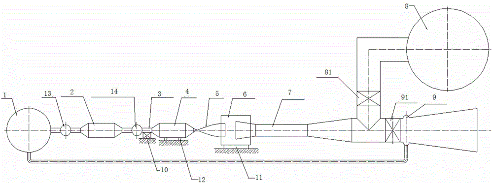
[0019] In the process layout of the existing wind tunnel, the fixed support bearing the axial force is placed under the front chamber, and the space for replacing the nozzle is obtained by moving the test section back and forth, which increases the structural complexity of the test section and needs to solve the problem of the test section. Section movement, positioning and sealing and other related issues; in addition, the super-expansion section needs to be equipped with a telescopic structure, and its sliding seal cannot meet the higher vacuum requirements. In terms of operation mode, existing wind tunnels only use blowing or blowing suction, and the height simulation capability of wind tunnels is limited. For this, see figure 1 , ...


PUM


Abstract

The invention discloses a process layout method for a conventional hypersonic speed wind tunnel. The process layout method includes the steps that a fixed supporting base for bearing axial force of components before a test section of the conventional hypersonic speed wind tunnel is arranged on a heat pipeline before a front chamber, the test section is fixed immovably, and axial force generated by an ultra-expanding section in the bearing test of the fixed supporting base is set; the front chamber can move toward the side of the axis of the conventional hypersonic speed wind tunnel to provide space for replacing a spray pipe; two branches are arranged behind the ultra-expanding section, one branch is provided with an ejector, and the other branch is led to a vacuum container, and the two branches are each provided with a valve used for switching and selecting the branches. Due to the technical scheme, the conventional hypersonic speed wind tunnel can have two operation modes, and the capacity for simulating the flight height of an air vehicle of the conventional hypersonic speed wind tunnel is greatly improved.

Description

technical field [0001] The invention belongs to the field of aerodynamics, in particular to a conventional hypersonic wind tunnel process layout method. Background technique [0002] A hypersonic wind tunnel refers to a wind tunnel with a Mach number range of 5 to 12 for the test air flow, which is used to reproduce the flight environment of a hypersonic aircraft. In this environment, the simulation test of the aircraft model is carried out, and relevant parameters are measured. From these tests Parameters get the aerodynamic parameters of the aircraft during flight. Conventional hypersonic wind tunnels usually use resistance or thermal storage heaters to increase the total temperature of the test airflow. Because the wind tunnel needs to consume a lot of power during operation, the hypersonic wind tunnel is mostly a temporary structure. The change of Mach number is mainly obtained by replacing different nozzles. The test section is a closed free jet type. In order to meet ...

Claims


Application Information

Patent Timeline
IPC IPC(8): G01M9/02
Inventor 孙勇堂石运军崔春
Owner BEIJING AEROSPACE YISEN WIND TUNNEL ENG TECH
Learn More