
An adjustable slope flow test device

A test device and slope flow technology, applied to measuring devices, instruments, scientific instruments, etc., can solve problems such as poor stability, no tail water design, and inability to truly reflect the spatial distribution characteristics of slope soil, achieving high stability , the effect of improving accuracy

Inactive Publication Date: 2017-04-05
SICHUAN UNIV
View PDF4 Cites 1 Cited by
  • Summary
  • Abstract
  • Description
  • Claims
  • Application Information

AI Technical Summary

Problems solved by technology

The existing slope flow test device has the following deficiencies: First, because the soil is directly laid on the smooth bottom of the tank during the test, the stability of the soil on the bottom is poor, and the soil is easily taken away by the water flow, resulting in slope flow. During the test, the accumulation thickness, slope and vegetation cover characteristics of the soil on the slope changed far from those in the actual environment, thus affecting the accuracy of the results of the slope flow test; secondly, because the existing slope flow test The device does not have a structure for the classification and collection of tail water, so it is used for slope flow tests. When collecting tail water, only the surface flow and the middle flow of the soil can be collected together, and the water flow characteristics of the surface flow and the middle flow of the soil and the erosion mechanism of the soil are different, the existing overland flow test device will also affect the accuracy of the overland flow test results for this reason; third, because the soil distribution characteristics on the actual slope often change along the slope with the slope direction, and The existing overland flow test device cannot realize the free combination of multiple slopes, so it is difficult to realize the simulation of the soil spatial distribution characteristics of multi-slope changes in the overland flow test, so it cannot truly reflect the actual slope soil spatial distribution characteristics on the overland flow. Impact of test results

Method used


Image

  • An adjustable slope flow test device
  • An adjustable slope flow test device
  • An adjustable slope flow test device

Examples


Embodiment 1

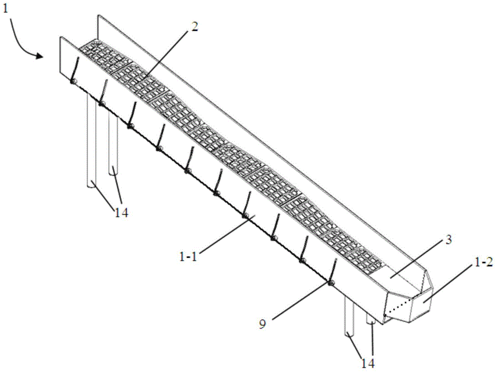
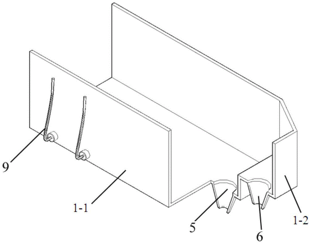
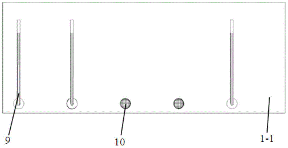
[0030] Such as figure 1 As shown, the structure of the adjustable slope flow test device provided in this embodiment includes a slope water tank 1, a soil fixing grid 2 with telescopic support feet 4, a panel 3 with telescopic support feet 4, and the The slope water tank 1 is an integrated groove composed of the basic water tank 1-1 and the surface flow collection tank 1-2 connected to the water outlet. The partial cross-sectional structure diagram of the slope water tank is shown in figure 2 , wherein the water inlet end of the basic water tank 1-1 is open and the water outlet end is closed, the first tailwater collection hole 5 is arranged at the bottom of the water outlet water tank, the water inlet end of the surface flow collection tank 1-2 is open, the water outlet end is closed, and the water inlet The bottom plate of the water end is connected to the top of the closed vertical plate at the outlet end of the basic water tank, and the second tailwater collection hole 6 ...

Embodiment 2

[0034] In this embodiment, the structure of the adjustable slope flow test device is as follows Figure 10 As shown, it includes a slope water tank 1, a soil fixing grid 2 with telescopic support feet 4, a panel 3 with telescopic support feet 4, a water supply tank 11 and a steady flow tank 12. The slope water tank 1 is an integrated groove composed of the basic water tank 1-1 and the surface flow collection tank 1-2 connected to the water outlet. The partial cross-sectional structure diagram of the slope water tank is shown in figure 2 , wherein the water inlet end of the basic water tank 1-1 is open and the water outlet end is closed, the first tailwater collection hole 5 is arranged at the bottom of the water outlet water tank, the water inlet end of the surface flow collection tank 1-2 is open, the water outlet end is closed, and the water inlet The bottom plate of the water end is connected to the top of the closed vertical plate at the outlet end of the basic water tank...


PUM


Abstract

The invention provides an adjustable type overland flow testing device which comprises an overland water tank as well as soil fixing grids and a surface plate, wherein the overland water tank is of an overland inclined structure supported by support columns; the soil fixing grids are provided with telescopic support feet; the surface plate is provided with telescopic support feet; the overland water tank is an integrated groove consisting of a base water tank and a surface flow collecting tank which is connected with the water outlet end of the base water tank; the water inlet end of the base water tank is opened; the water outlet end of the base water tank is sealed; first tail water collecting holes are formed in the bottom of the water outlet end of the base water tank; the water inlet end of the surface flow collecting tank is opened; the water outlet end of the surface flow collecting tank is sealed; a bottom plate at the water inlet end is connected with the top end of a vertical sealing plate at the water outlet end of the base water tank; second tail water collecting holes are formed in the bottom plate; the soil fixing grids are arranged on the bottom plate of the base water tank; the surface plate is arranged on the bottom plate on one side of the water outlet end of the base water tank; one end of the surface plate is connected with the soil fixing grids; the other end of the surface plate is connected with the bottom plate of the surface flow collecting tank; a first screening net is arranged between the bottom plate at the water outlet end of the base water tank and the surface plate with the telescopic support feet.

Description

technical field [0001] The invention belongs to the technical field of slope flow test devices, in particular to an adjustable slope flow test device. Background technique [0002] Slope soil erosion is an important link in the process of water and soil loss. Field monitoring and laboratory experiments are the main means to study the characteristics of slope water flow and soil erosion mechanism. Slope soil is affected by various factors such as soil-forming reasons, landform characteristics, and water flow conditions. The actual slope soil and slope often change along the slope direction, and its soil composition, accumulation thickness, and slope cover characteristics also vary. difference. In order to deeply understand the movement characteristics of slope water flow and its soil erosion transport mechanism, the slope flow test is the most important research method at present. Due to the influence of natural conditions on field monitoring, it is difficult to guarantee t...

Claims


Application Information

Patent Timeline
Patent Type & Authority Patents(China)
IPC IPC(8): G01N17/00
Inventor 王协康刘兴年刘同宦叶龙周苏芬
Owner SICHUAN UNIV
Learn More