
Laser light source and projection display device

A technology of laser light sources and lasers, applied in the field of laser light sources, can solve the problems of large laser light source structures, etc., and achieve the effect of shortening optical distance and compact position arrangement

Active Publication Date: 2015-03-25
QINGDAO HISENSE LASER DISPLAY CO LTD
View PDF8 Cites 0 Cited by
  • Summary
  • Abstract
  • Description
  • Claims
  • Application Information

AI Technical Summary

Problems solved by technology

[0010] The purpose of the present invention is to provide a laser light source and a projection display device to solve the problem of large laser light source structure

Method used


Image

  • Laser light source and projection display device
  • Laser light source and projection display device
  • Laser light source and projection display device

Examples


Embodiment Construction

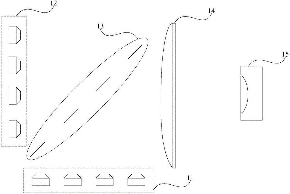
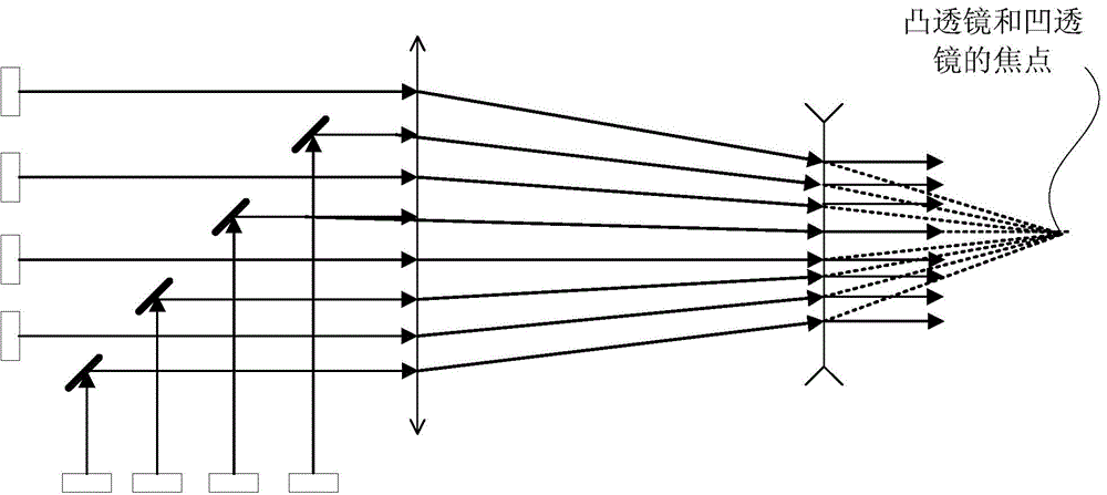
[0031] The core idea of ​​the present invention is that the convex lens is arranged between the laser and the convex lens, so that the light beam emitted by the laser is firstly shaped by the convex lens, and the horizontal and / or vertical dimensions of the light beam emitted by each group of lasers are adjusted, and then the reflector unit performs two secondary plastic surgery.

[0032] The laser light source provided by the embodiment of the present invention includes: N groups of lasers, N convex lenses, at least one mirror unit, and a concave lens; each convex lens corresponds to a group of lasers, and is used to converge the beams emitted by the corresponding group of lasers; each The reflector unit corresponds to at least one convex lens, which is arranged in the outgoing light direction of the corresponding convex lens, and the concave lens is arranged in the outgoing light direction of the at least one reflective mirror unit; the light beams emitted by each convex lens...


PUM


Abstract

The invention discloses a laser light source and a projection display device. The laser light source comprises N sets of laser devices, N convex lenses, at least one reflector unit and a concave lens. Each convex lens corresponds to one group of laser devices and is used for converging light beams emitted by the corresponding group of laser devices. Each reflector unit corresponds to at least one convex lens and is arranged in the emergent light direction of the corresponding convex lens. The concave lens is arranged in the emergent light direction of the reflector units. Light emitted by the convex lens corresponding to each reflector unit passes through the reflector unit and then reaches the concave lens. According to the structure, the distance between optical devices is reduced, so that the size of the laser light source is effectively reduced, the problem that an existing laser light source and a product (such as a projector) with the laser light source are large in size is solved, and then the production cost is reduced.

Description

[0001] This application claims the priority of the Chinese patent application with the application number 201410461168.2 and the title of the invention "a laser light source and projection display device" submitted to the China Patent Office on September 11, 2014, the entire contents of which are incorporated in this application by reference middle. technical field [0002] The invention relates to the technical field of laser light sources, in particular to a laser light source and a projection display device. Background technique [0003] In recent years, more and more projection display products (hereinafter referred to as projectors) begin to use laser light sources. The working principle of a laser light source is to use a laser to excite phosphors. Usually, low-power lasers are used to form a laser array, and after the laser light power reaches tens of watts or higher, a beam of light is synthesized by a beam shaping device, and this beam of laser is used to excite ph...

Claims


Application Information

Patent Timeline
Patent Type & Authority Applications(China)
IPC IPC(8): G03B21/20G02B27/09
CPCG03B21/208G03B21/2066G03B21/2073H01S5/005H01S5/0071H01S5/4012H04N9/3161H04N9/3164G03B21/2033G02B27/0955G02B27/0977
Inventor 刘洪岩李巍刘显荣田有良
Owner QINGDAO HISENSE LASER DISPLAY CO LTD
Learn More