Developing roller and process cartridge

A technology for developing rollers and process boxes, which is applied in the field of parts and components, and can solve problems such as the large diameter of the metal mandrel and restrictions on the selection of materials for the foaming layer.

Active Publication Date: 2021-05-18
PROSPECT IMAGE PROD LIMITED OF ZHUHAI
View PDF13 Cites 0 Cited by
  • Summary
  • Abstract
  • Description
  • Claims
  • Application Information

AI Technical Summary

Problems solved by technology

However, in order to make the resistivity and hardness of the non-metallic conductive foaming layer meet the corresponding requirements, the selection of foaming layer materials is limited; in addition, there are still problems of corresponding deformation and large diameter of the metal mandrel.

Method used


Image

  • Developing roller and process cartridge
  • Developing roller and process cartridge
  • Developing roller and process cartridge

Examples


no. 1 example

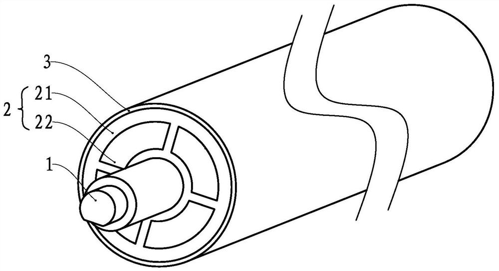
[0029] see image 3 , The developing roller is composed of a metal mandrel 1, an intermediate layer 2 and a conductive elastic layer 3, the intermediate layer 2 is composed of a supporting structure 21 and a conductive structure 22, the intermediate layer 2 is set outside the metal mandrel 1, and the conductive elastic layer 3 is set in the middle Layer 2 outside.

[0030] see Figure 4 to Figure 6 , the support structure 21 is composed of an inner support cylinder 211, an outer support cylinder 212, and spokes 213 connecting the inner support cylinder 211 and the outer support cylinder 212; Extending to the other axial end; the inner support cylinder 211 is formed with 8 rows of first through holes 2111 arranged radially along the developing roller, and the outer support cylinder 212 is formed with 8 rows of second through holes arranged radially along the developing roller 2121; the conductive structure 22 is a conductor filled between the inner support cylinder 211 and th...

no. 2 example

[0034] As a description of the second embodiment of the developing roller of the present invention, only the differences from the first embodiment of the developing roller described above will be described below.

[0035] A hollow metal mandrel is used instead of a solid metal mandrel.

[0036] Process cartridge first embodiment

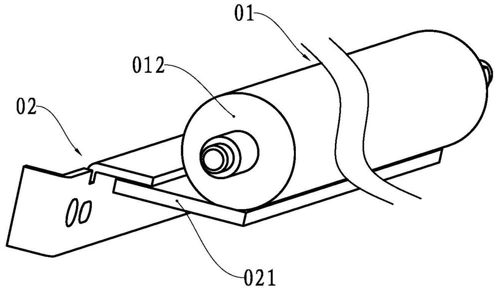
[0037] The process cartridge has a casing and a developing roller rotatably supported on both ends of the casing, wherein the developing roller is the developing roller in the first embodiment of the above-mentioned developing roller.

[0038] Process cartridge second embodiment

[0039] As a description of the second embodiment of the process cartridge according to the present invention, only the points of difference from the above-mentioned first embodiment of the process cartridge will be described below.

[0040] Wherein the developing roller adopts the developing roller in the second embodiment of the above-mentioned developing roller.

[004...


PUM


Abstract

The invention relates to a developing roller, which includes a metal mandrel, an intermediate layer and a conductive elastic layer; the intermediate layer includes a support structure and a conductive structure; the support structure is made of hard materials in an integrated manner, and the support structure includes an inner support cylinder , the outer support tube and the spokes connecting the inner support tube and the outer support tube, the inner support tube is set outside the metal mandrel, and the conductive elastic layer is set outside the outer support tube; the inner support tube is formed with a plurality of radially arranged first A through hole, a plurality of radially arranged second through holes are formed on the outer support cylinder; along the axial direction of the developing roller, the spokes extend from one axial end of the intermediate layer to the other axial end of the intermediate layer; conductive The structure is a conductor filled between the inner support cylinder and the outer support cylinder, and in the first through hole and the second through hole, and the conductive elastic layer is electrically connected with the mandrel through the conductor. The developing roller has the advantages of low cost, small deformation of the conductive elastic layer and the like. Furthermore, the present invention also relates to a process cartridge using the above developing roller.

Description

technical field [0001] The present invention relates to a component of an electrophotographic image forming device, in particular to a developing roller and a process box using the developing roller. Background technique [0002] Electrophotographic imaging devices such as laser printers all use a process box detachably installed therein. The process box has a housing and a developing roller rotatably supported at both ends of the housing. In order to ensure that the carbon powder formed on the working surface of the developing roller To be able to be uniform in thickness, a powder knife needs to be installed near the developing roller. Through the rotation of the developing roller and the extrusion of the powder knife, the toner between the developing roller and the powder knife is charged due to friction and the thickness is evenly distributed on the developing roller. roller work surface. [0003] see figure 1 , an existing developing roller 01 is composed of a metal ma...

Claims


Application Information

Patent Timeline
Patent Type & Authority Patents(China)
IPC IPC(8): G03G15/08G03G21/18
CPCG03G15/0808G03G21/18
Inventor 陈亮高瑞祺
Owner PROSPECT IMAGE PROD LIMITED OF ZHUHAI
Why Eureka
Try Eureka