Display device

A display device and display technology, applied in the field of display screens, can solve problems such as affecting the observation effect and inconsistency in edge pixel sizes, and achieve the effect of seamless splicing of displayed images, saving adjustment steps, and ensuring consistency.

Inactive Publication Date: 2015-03-25
GUANGDONG VTRON TECH CO LTD
View PDF5 Cites 14 Cited by
  • Summary
  • Abstract
  • Description
  • Claims
  • Application Information

AI Technical Summary

Problems solved by technology

Moreover, this solution only enlarges the edge pixels and enlarges the display surface, but the size of the edge pixels is inconsistent with the central pixel, which affects the observation effect. In the future, it is necessary to adjust the pixel density or brightness of the central area and the edge area to achieve the consistency of the display as much as possible.

Method used


Image

  • Display device
  • Display device
  • Display device

Examples


Embodiment 1

[0037] Such as Figure 7 and 8 Shown is a schematic structural diagram of a specific embodiment of a display device of the present invention. see Figure 7 and 8 In this specific embodiment, a display device includes a display 6 having a display surface 61 and a frame 62 on it, and an optical microlens array 7 including several microlenses is arranged above the display 6, and the light emitted from the display 6 passes through the optical microlens. Near the focal plane position of each microlens in the array 7 is incident into the optical microlens array 7 , and a scattering screen 8 is arranged above the optical microlens array 7 .

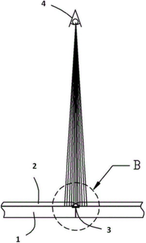
[0038] Such as Figure 9 As shown, the light 4 emitted by the display surface 61 of the display 6 enters the microlens near the focal plane position of the microlens of the optical microlens array 7, and after imaging through the microlens, the light 4 will be in a certain direction with the normal direction of the display 6. The angles are...

Embodiment 2

[0049] Different from Embodiment 1, the microlenses in the optical microlens array 7 in this specific embodiment adopt biconvex microlenses, such as Figure 16 shown. Schematic diagram of the structure of a display device using biconvex microlenses to form an optical microlens array. Figure 17 shown.

[0050] In a preferred embodiment, the lenticular lenses are surrounded by light-absorbing materials to prevent crosstalk between the light rays between the lenses and cause image confusion on the scattering screen 8 .

Embodiment 3

[0052] The principle of realizing the seamless splicing display of the display device provided by this specific embodiment is completely the same as that of Embodiment 1 or 2, and will not be repeated here. The difference is that the microlens in the optical microlens array provided by this embodiment is a plano-convex lens structure, such as Figure 18 shown. The plano-convex lenses are surrounded by light-absorbing materials to prevent crosstalk between the light rays between the lenses and cause image confusion on the scattering screen 8 .

[0053] Preferably, the structural size of the plano-convex lens can be adjusted so that the focal plane of the plano-convex lens is located at the planar end of the lens. When the focal plane of the plano-convex lens is located at the plane end of the lens, the plane end of the plano-convex lens can be directly mounted against the display surface 61 of the display 6, thereby greatly simplifying the installation process of the optical m...


PUM


Abstract

The invention relates to the field of display screens, in particular to a display device. The display device comprises a displayer provided with a display surface and a frame. An optical microlens array including a plurality of microlenses is arranged above the displayer. Light rays emitted from the displayer are irradiated into the optical microlens array from positions near to focal plane positions of the microlenses in the optical microlens array. A scattering screen is arranged above the optical microlens array. The display device has the advantages that the optical microlens array and the scattering screen are arranged on the surface of the displayer additionally, and image information from the displayer are shifted and amplified and can cover the frame of the displayer to shield the frame of the displayer, so that splicing seams among splicing units can be eliminated completely when the display device is applied to a spliced display screen, seamless splicing is achieved, and display images are complete, continuous and free from split sensation; on the basis of the scattering effect of the scattering screen, the complete and continuous image information can be still viewed and does not distorted when being viewed from wide angles.

Description

technical field [0001] The present invention relates to the field of display screens, and more specifically, to a display device. Background technique [0002] At present, the demand for various ultra-large-size display screens is increasing day by day, and its applications are becoming more and more extensive, and splicing display is a main way to realize ultra-large-screen display. At present, flat-panel displays with low cost advantages (such as LCD displays) often have "frames", that is, there are non-image display areas on the edges. Therefore, large-scale spliced ​​display devices composed of spliced ​​​​displays have splicing seams that seriously divide the overall screen. , which seriously affects the overall effect of the spliced ​​display screen, and this problem also exists in the spliced ​​display of the plasma display device. [0003] Such as figure 1 Shown is the general structure of the front of the flat panel display. The front structure of the flat panel d...

Claims


Application Information

Patent Timeline
IPC IPC(8): G09F9/30G02B3/00
CPCG09F9/30G02B3/0006
Inventor 丁家磊潘嘉强
Owner GUANGDONG VTRON TECH CO LTD
Why Eureka
Try Eureka