A chain-staggered microchannel structure

A micro-channel structure, micro-fluid channel technology, applied in electrical components, electric solid devices, circuits, etc., can solve the problems of low heat dissipation performance, low heat exchange efficiency, multi-pump power, etc. Increased length, enhanced fluid mixing

Active Publication Date: 2017-11-24
XIDIAN UNIV
View PDF2 Cites 0 Cited by
  • Summary
  • Abstract
  • Description
  • Claims
  • Application Information

AI Technical Summary

Problems solved by technology

[0007] 1) When the cooling working fluid flows through the heated long flat channel, the working fluid absorbs the heat transferred from the heat source to the side wall of the channel, so that the temperature of the working fluid increases continuously with the flow direction, and the temperature uniformity of the heating surface is not good. good
[0008] 2) When the fluid flows through the flat channel, with the formation and development of the thermal boundary layer, the convective heat transfer coefficient decreases with the flow direction, and the heat transfer efficiency is not high
[0011] 1) The flow channel of the microchannel is relatively long, which will consume more pump power and lower heat transfer efficiency
[0012] 2) When the fluid flows through the curved flow channel, the fluid mixing in the adjacent flow channel is insufficient, and the heat dissipation performance is low

Method used


Image

  • A chain-staggered microchannel structure
  • A chain-staggered microchannel structure
  • A chain-staggered microchannel structure

Examples


Embodiment Construction

[0034] In order to make the object, technical solution and advantages of the present invention clearer, the present invention will be further described in detail below in combination with specific examples and with reference to the accompanying drawings. It should be understood that these descriptions are exemplary only, and are not intended to limit the scope of the present invention. Also, in the following description, descriptions of well-known structures and techniques are omitted to avoid unnecessarily obscuring the concept of the present invention.

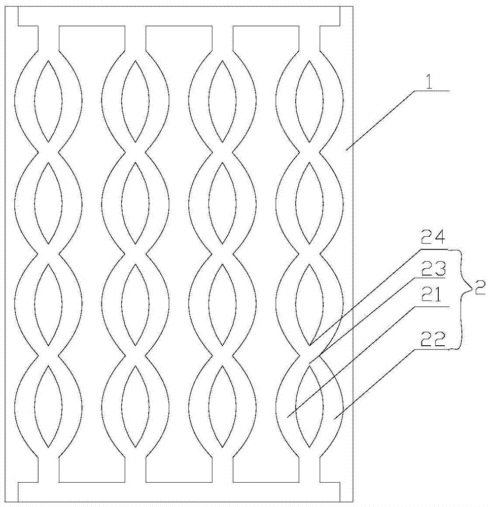
[0035] Such as image 3 Shown: a chain interlaced microchannel structure includes a substrate 1 and a microfluidic channel 2 arranged on the substrate 1, the microfluidic channel 2 includes two microfluidic branch channels 21, 22, and the two microfluidic channels The fluid branch channels 21 and 22 periodically intersect and separate from each other, and the two microfluid branch channels 21 and 22 respectively form an int...


PUM


Abstract

The invention discloses a chain interlaced microchannel structure, which includes a substrate and a microfluidic channel arranged on the substrate, and is characterized in that the microfluidic channel includes two microfluidic branch channels, and the two microfluidic channel The fluid branch channels intersect and separate periodically, and the two microfluid branch channels respectively form an intersection and a bifurcation at the mutual intersection and separation. In the microfluidic channel provided by the present invention, the curved microchannel is a periodically changing arc-shaped flow channel, which is smoothly connected by circular arcs of different radians. Two adjacent flow channels are symmetrical and cross at intervals. After crossing The runners are arranged in arcs. The cooling medium flows smoothly in the flow channel, and the coefficient of frictional resistance is small. The interleaving of the two microfluidic branch channels of each microfluidic channel causes the redevelopment of the thermal boundary layer at the leading edge of the flow channel, reducing the thickness of the boundary layer, and the regenerated inlet effect keeps the fluid in a developed state, improving heat dissipation The heat dissipation performance of the device.

Description

technical field [0001] The invention belongs to the field of microelectronic high-power chip package heat dissipation, and in particular relates to a chain-type interlaced micro-channel structure. Background technique [0002] With the increasing number of semiconductors in integrated circuits and the miniaturization of packaging volume, the heat generation per unit volume of the chip is increasing significantly. If the heat cannot be effectively dissipated in a short time, it will have a negative impact on the life and performance of semiconductor devices. big impact. [0003] Traditional heat transfer methods include: air-cooled heat dissipation, water-cooled heat dissipation, heat pipe heat dissipation, thermoelectric cooling, micro-jet cooling and micro-channel cooling. Air-cooled heat dissipation has low cost and obvious heat dissipation effect, but due to the use of mechanical components, large volume and high noise, it cannot meet the heat dissipation requirements of...

Claims


Application Information

Patent Timeline
Patent Type & Authority Patents(China)
IPC IPC(8): H01L23/473H01L23/367
Inventor 田文超卫三娟
Owner XIDIAN UNIV
Why Eureka
Try Eureka