Transient state phase-shifting control method for double-drive full-bridge DC/DC converter

A technology of DC converter and dual-active full bridge, which is applied in the direction of converting DC power input to DC power output, control/regulation systems, instruments, etc., which can solve the phenomenon of DC bias, increase the size and cost of the converter, and increase the power Loss and other issues to achieve the effect of eliminating DC bias, improving dynamic response speed, and reducing current impact

Active Publication Date: 2015-03-25
SHENZHEN POWER SUPPLY BUREAU +1
View PDF4 Cites 22 Cited by
  • Summary
  • Abstract
  • Description
  • Claims
  • Application Information

AI Technical Summary

Problems solved by technology

In the steady-state process, the dual-active full-bridge DC converter can meet the above premise, but in the transient process, it cannot strictly meet this premise
Especially when the phase shift angle changes, the voltage across the transformer is asymmetrical between two switching cycles, which in turn causes the volt-second product of the voltage across the transformer to be non-zero, which also leads to the occurrence of...

Method used


Image

  • Transient state phase-shifting control method for double-drive full-bridge DC/DC converter
  • Transient state phase-shifting control method for double-drive full-bridge DC/DC converter
  • Transient state phase-shifting control method for double-drive full-bridge DC/DC converter

Examples


Embodiment Construction

[0019] The specific embodiments of the present invention will be described in detail below in conjunction with the technical solution of the present invention and the accompanying drawings.

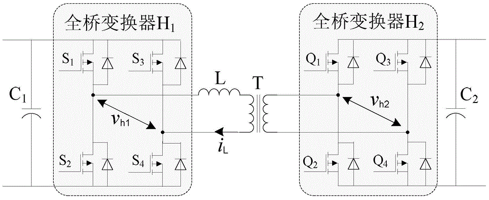
[0020] The topological structure of the dual active full-bridge DC converter in the present invention is as follows figure 1 Shown. The converter is mainly composed of two full-bridge converters H 1 And H 2 , Two DC filter capacitors C 1 And C 2 , A high-frequency inductor L and a high-frequency isolation transformer T composition.

[0021] Two DC filter capacitors C in the system embodiment of the present invention 1 And C 2 Both are 2200μF, the auxiliary inductance L is 0.18mH, and the switching frequency of the switch tube is 20kHz.

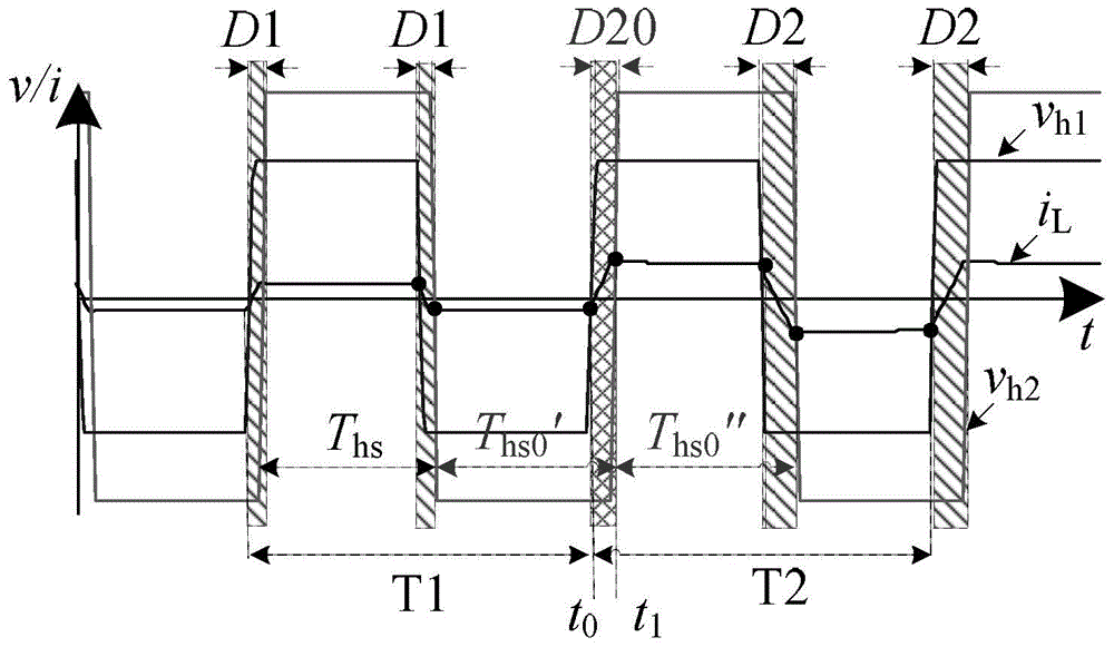
[0022] The transient phase shift control method for dual active full bridge DC converter of the present invention is as follows figure 2 Shown. i L Is the current flowing in the high-frequency inductor L. T1 is the first switching period, T2 is the second swi...


PUM


Abstract

The invention discloses a transient state phase-shifting control method for a double-drive full-bridge DC/DC converter and belongs to the field of power and electronic technologies. The method includes the steps that at a steady state period, an AC output side of a first full-bridge of the double-drive full-bridge DC/DC converter is adjusted to be a square wave vh1 with the duty ratio being 50%, and a phase position is fixed; an AC output side of a second full-bridge of the double-drive full-bridge DC/DC converter is also adjusted to be a square wave vh2 with the duty ratio being 50%, equal phase-shifting angles are arranged between the rising edges of the square wave vh1 and the square wave vh2 and between the falling edges of the square wave vh1 and the square wave vh2 respectively; at a transient state time period, the phase-shifting angles are changed from phase-shifting angles D1 of a first switching period T1 to phase-shifting angles D2 of a second switching period T2, in the second switching period T2, the phase-shifting angle between the rising edge (or the falling edge) of the square wave vh2 and the falling edge (or the rising edge) of the square wave vh1 is adjusted to be a phase-shifting angle D20, and the phase-shifting angle between the falling edge (or the rising edge) of the square wave vh2 and the rising edge (or the falling edge) of the square wave vh1 is the phase-shifting angle D20. The transient state phase-shifting control method for the full-bridge DC/DC converter can reduce current shock and accelerate dynamic response.

Description

Technical field [0001] The invention belongs to the technical field of power electronics, and relates to a dual-active full-bridge DC converter, in particular to a transient phase shift control method for the dual-active full-bridge DC converter. Background technique [0002] The dual active full-bridge DC converter is a DC converter that can operate in two quadrants. Its topological structure is like figure 1 As shown, the converter mainly consists of two full-bridge converters H 1 And H 2 , Two DC filter capacitors C 1 And C 2 , A high-frequency inductor L and a high-frequency isolation transformer T composition. Since it is functionally equivalent to two unidirectional DC converters, it can greatly reduce the size, weight and cost of the system. It is widely used in DC motor drives, uninterruptible power supplies and electric vehicles that require bidirectional energy flow. [0003] At present, the research directions of dual active full-bridge DC converters at home and abroad ...

Claims


Application Information

Patent Timeline
IPC IPC(8): H02M3/335
CPCH02M3/3353H02M1/0006
Inventor 赵彪宋强刘文华刘国伟赵宇明姚森敬
Owner SHENZHEN POWER SUPPLY BUREAU
Why Eureka
Try Eureka