Single electric signal excitation ultrasonic elliptic vibration multi-vibrator bidirectional material conveying device

A technology of elliptical vibration and single electric signal, which is applied in vibrating conveyors, conveyors, transportation and packaging, etc., can solve the problems of restricting the overall performance of the precision transmission system, the difficulty of long-distance transportation, and the difficulty of precise closed-loop control, etc., to achieve simplification Control circuit and ultrasonic power supply structure, stable vibration performance and simple structure

Inactive Publication Date: 2015-03-25
SUZHOU UNIV OF SCI & TECH
View PDF7 Cites 0 Cited by
  • Summary
  • Abstract
  • Description
  • Claims
  • Application Information

AI Technical Summary

Problems solved by technology

[0002] In the fields of automatic production, processing and assembly of medicine, chemical industry, food, machinery, material preparation, etc., the transmission and assembly of materials and parts have been using traditional low-frequency and high-amplitude electromagnetic vibration transmission devices. This device has more noise when working. Low delivery accuracy, difficult to achieve precise closed-loop control, and small power volume, these problems have always restricted the improvement o

Method used


Image

  • Single electric signal excitation ultrasonic elliptic vibration multi-vibrator bidirectional material conveying device
  • Single electric signal excitation ultrasonic elliptic vibration multi-vibrator bidirectional material conveying device
  • Single electric signal excitation ultrasonic elliptic vibration multi-vibrator bidirectional material conveying device

Examples


Embodiment Construction

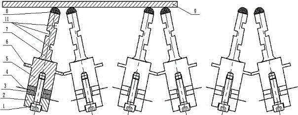
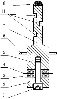
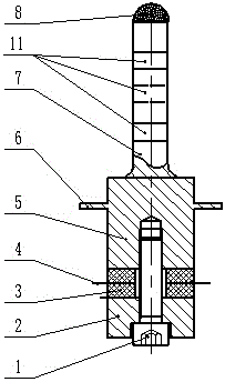
[0021] combine figure 1 , 2 , 3, a single electric signal excitation ultrasonic elliptical vibration multi-vibrator two-way material conveying device, which uses 10 vibrators as the exciter, and every 5 vibrators are divided into groups, and the two groups of vibrators alternately face each other along the direction of conveying materials Arranged in a single row in a straight line. Each vibrator includes an ultrasonic vibration transducer, an elliptical vibration mode converter 7 and a friction drive block 8; the outer contour of the ultrasonic vibration transducer is cylindrical, which includes a bolt 1 and a back cover that is sequentially sleeved on the bolt 1 2. The piezoelectric ceramic sheet 3, the electrode sheet 4 and the front cover 5, the front cover 5 is provided with a flange 6 that can be connected with other structural devices, the rear cover 2 and the front cover 5 are connected by bolts 1 The rear cover plate 2, the piezoelectric ceramic sheet 3, the electro...


PUM


Abstract

The invention discloses a single electric signal excitation ultrasonic elliptic vibration multi-vibrator bidirectional material conveying device which is mainly applied to accurate and precise conveying of strip-shaped materials. According to the single electric signal excitation ultrasonic elliptic vibration multi-vibrator bidirectional material conveying device, multiple vibrators are adopted as shock excitation bodies and divided into two sets, and the two sets of vibrators are arranged in an alternated opposite mode. Each vibrator comprises an ultrasonic vibration energy converter, an elliptic vibration mode converter and a friction driving block arranged at the front end of the elliptic vibration mode converter. Each ultrasonic vibration energy converter comprises a bolt, a rear cover plate, a piezoelectric ceramic piece, an electrode plate and a front cover plate, wherein the rear cover plate, the piezoelectric ceramic piece, the electrode plate and the front cover plate are arranged on the bolt in sequence in a sleeving mode. The rear cover plates, the piezoelectric ceramic pieces, the electrode plates and the front cover plates are connected and pressed through the rear cover plates, the front cover plates and the bolts. Each elliptic vibration mode converter is arranged at the front end of the corresponding ultrasonic vibration energy converter and is integrally cylindrical, and three rectangular notches which are distributed in a staggered mode are formed in the left side and the right side of each elliptic vibration mode converter.

Description

technical field [0001] The invention relates to the field of vibration precision conveying using the inverse piezoelectric effect of piezoelectric ceramics, in particular to a multi-vibrator material bidirectional conveying device driven by ultrasonic elliptical vibration generated by excitation of a single electric signal. Background technique [0002] In the fields of automatic production, processing and assembly of medicine, chemical industry, food, machinery, material preparation, etc., the transmission and assembly of materials and parts have been using traditional low-frequency and high-amplitude electromagnetic vibration transmission devices. This device has more noise when working. The distribution accuracy is low, it is not easy to realize precise closed-loop control, and the power volume is small. These problems have always restricted the improvement of the overall performance of the precision transmission system. [0003] The rapid development and application of u...

Claims


Application Information

Patent Timeline
IPC IPC(8): H02N2/00B65G27/16
Inventor 吴永芝殷振李艳刘义生
Owner SUZHOU UNIV OF SCI & TECH
Why Eureka
Try Eureka