Movable suction box

A technology of box body and annular suction nozzle, which is applied in the direction of cleaning methods, cleaning methods and utensils, chemical instruments and methods using gas flow, etc., which can solve the problems of failure to meet the normal use of equipment, fatigue aging of telescopic hoses, cracking and leakage, etc. , to achieve the effect of thorough dust collection, simple structure and small ventilation resistance

Active Publication Date: 2015-04-01
JIANGSU JINGYA ENVIRONMENT TECH
View PDF8 Cites 0 Cited by
  • Summary
  • Abstract
  • Description
  • Claims
  • Application Information

AI Technical Summary

Problems solved by technology

[0002] At present, the traditional form of suction box is that the suction nozzle is directly or indirectly connected to the telescopic hose. Due to the rapid and frequent movement of the suction nozzle, there is a problem of cra

Method used


Image

  • Movable suction box
  • Movable suction box

Examples


Embodiment Construction

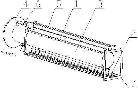
[0037] see figure 1 , figure 2 , a movable suction box of the present invention, which includes a box body 1, the front end of the box body 1 is sealed, and the rear end is provided with a connection port 7, and a linear guide rail 2 is provided along the horizontal direction in the box body 1, and the linear guide rail 2 is provided with a sliding air duct 3, the front end of the sliding air duct 3 extends out of the box body 1 and the end is provided with an annular suction nozzle 4, the top of the box body 1 is provided with a cylinder 5, and one end of the cylinder 5 is connected to the box body 1 is fixedly connected, and the other end of the cylinder 1 is fixedly connected with the sliding air duct 3 or the annular suction nozzle 4 through the connecting piece 6.

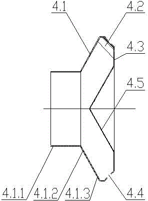
[0038] The annular suction nozzle 4 includes a support cylinder 4.1 and a front plate 4.3, the front plate 4.3 is fixedly arranged on the front side of the support cylinder 4.1, and an annular slit suction p...


PUM

PropertyMeasurementUnit
Cone angleaaaaaaaaaa

Abstract

The invention relates to a movable suction box, and belongs to the technical field of dust collection equipment. The movable suction box comprises a box body (1), wherein the front end of the box body (1) is sealed, and a connection opening (7) is formed in the rear end of the box body (1); a linear guide rail (2) is arranged in the box body (1) along the horizontal direction; a sliding air pipe (3) is arranged on the linear guide rail (2); the front end of the sliding air pipe extends out of the box body (1) and is provided with an annular suction nozzle (4); a cylinder (5) is arranged between the box body (1) and the sliding air pipe (3) or the annular suction nozzle (4) in a connection manner; under the action of the cylinder (5), the sliding air pipe (3) can do reciprocating motion on the linear guide rail (2). The movable suction box disclosed by the invention is simple in structure and can meet the requirements on pipeline sealing during quick moving of the suction nozzle and the service life.

Description

technical field [0001] The invention relates to a movable suction box, which belongs to the technical field of dust removal equipment. Background technique [0002] At present, the traditional form of suction box is that the suction nozzle is directly or indirectly connected to the telescopic hose. Due to the rapid and frequent movement of the suction nozzle, there is a problem of cracking and leakage caused by the fatigue and aging of the telescopic hose, especially when the suction nozzle has a large moving stroke. Due to the influence of its own gravity, it cannot meet the normal use of the equipment. Contents of the invention [0003] The purpose of the present invention is to overcome the above disadvantages and provide a movable suction box with a simple structure, which can meet the requirements of pipeline sealing and service life during the rapid movement of the suction nozzle. [0004] The object of the present invention is achieved as follows: a movable suction...

Claims


Application Information

Patent Timeline
IPC IPC(8): B08B5/04
CPCB08B5/04B08B13/00
Inventor 尚华杨志张立帅肖宏强
Owner JIANGSU JINGYA ENVIRONMENT TECH
Why Eureka
Try Eureka