
A tool holder for lathe with polishing function

A technology of lathes and tool holders, which is applied in the field of lathes, can solve the problems of inability to turn and grind the inner holes of workpieces, and achieve the effects of preventing slipping, convenient adjustment, and good stability

Active Publication Date: 2017-02-22
SUZHOU LU LU SHUN ELECTRICAL EQUIP
View PDF7 Cites 0 Cited by
  • Summary
  • Abstract
  • Description
  • Claims
  • Application Information

AI Technical Summary

Problems solved by technology

[0009] The technical problem to be solved by the present invention is: to overcome the technical problem that the traditional lathe in the prior art cannot turn and polish the inner hole of the workpiece, and provide an extended structure of the lathe, so that the workpiece can be polished while turning

Method used


Image

  • A tool holder for lathe with polishing function
  • A tool holder for lathe with polishing function
  • A tool holder for lathe with polishing function

Examples


Embodiment Construction

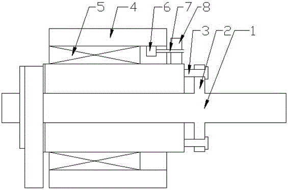
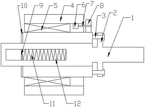
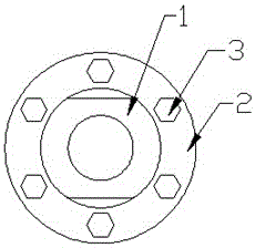
[0034] The present invention is described in further detail now in conjunction with accompanying drawing. These drawings are all simplified schematic diagrams, which only illustrate the basic structure of the present invention in a schematic manner, so they only show the configurations related to the present invention.

[0035] Such as figure 1 , figure 2 and image 3 As shown, the present invention is a lathe tool holder with polishing function, including a sliding plate 1 for installing a tool, a top pressing block and a top pressing assembly, and the sliding plate 1 is provided with an elongated groove 12 , the pressing block is sleeved on the sliding plate 1, the pressing assembly is fixed on the side of the sliding plate 1 facing away from the elongated groove 12, and the pressing assembly includes a fixing ring 2 fixed to the sliding plate 1 and a push ring, the push ring is movably connected with the fixed ring 2 through several screw assemblies 3, the cutter is ver...


PUM


Abstract

The invention relates to a cutter rest for a lathe with a polishing function. The cutter rest comprises a sliding plate, a jacking and pressing block and a jacking and pressing assembly, wherein the sliding plate is used for installing a cutter tool, a long strip-shaped groove is formed in the sliding plate, the jacking and pressing block is connected onto the sliding plate in a sleeving way, the jacking and pressing assembly is fixedly arranged at one side, opposite to the long strip-shaped groove, of the sliding plate, the jacking and pressing assembly comprises a fixing ring and a pushing ring, the fixing ring is fixed with the sliding plate, the pushing ring is movably connected with the fixing ring through a plurality of screw rod assemblies, the cutter tool is vertically arranged into the long strip-shaped groove relative to the sliding plate, one side surface of the cutter tool is tightly pressed on one side of the long strip-shaped groove, the pushing ring moves through regulating the screw rod assemblies, and the jacking and pressing block is tightly pressed onto the other side surface of the cutter tool; a polishing grinding wheel is connected onto the jacking and pressing block in a sleeving way, and the polishing grinding wheel and the jacking and pressing block are rotationally connected; and a motor is also arranged on the sliding plate, and drives the polishing grinding wheel to rotate through a transmission assembly.

Description

technical field [0001] The invention relates to a tool holder for a lathe with a polishing function, which belongs to the field of lathes. Background technique [0002] Generally, after boring a workpiece with a round hole, in order to improve the installation accuracy and aesthetics, it is often necessary to polish the inner wall of the hole, and these tasks are generally to re-clamp the workpiece to some special polishing machine for polishing. However, there are many problems in this polishing method; [0003] 1. When the workpiece is removed from the lathe and re-clamped on the polishing machine, it is difficult to ensure the coaxiality of the two installations because of the second installation. If it is a preliminary polishing, the surface of the polishing head is relatively rough , will bring a certain degree of wear to the inner wall of the hole, and non-coaxial wear will affect the accuracy of the hole. [0004] 2. Re-clamping will bring about a large waste of tim...

Claims


Application Information

Patent Timeline
Patent Type & Authority Patents(China)
IPC IPC(8): B23B11/00B23B21/00
CPCB23B29/04B23P23/04
Inventor 郭丽娟
Owner SUZHOU LU LU SHUN ELECTRICAL EQUIP
Learn More