
Vacuum suction cup machining clamp and using method thereof

A vacuum suction cup and vacuum adsorption technology, which is applied in the direction of manufacturing tools, metal processing equipment, metal processing machinery parts, etc., can solve the problems of digging cavity thickness, easy deformation, etc., and achieve the effect of ensuring flatness

Inactive Publication Date: 2015-04-01
SUZHOU IND PARK YIDA PRECISION ENG CO LTD
View PDF5 Cites 22 Cited by
  • Summary
  • Abstract
  • Description
  • Claims
  • Application Information

AI Technical Summary

Problems solved by technology

[0004] In view of the above-mentioned shortcomings of the prior art, the purpose of the present invention is to provide a vacuum suction cup processing jig and its use method, which can solve the problem that the current product needs to dig a cavity and is small in thickness and easy to deform

Method used


Image

  • Vacuum suction cup machining clamp and using method thereof
  • Vacuum suction cup machining clamp and using method thereof
  • Vacuum suction cup machining clamp and using method thereof

Examples


Embodiment Construction

[0030] The following specific examples illustrate the implementation of the present invention. Those skilled in the art can easily understand other advantages and effects of the present invention from the content disclosed in this specification.

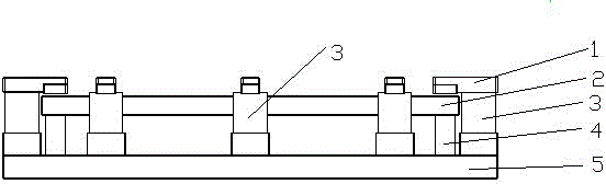
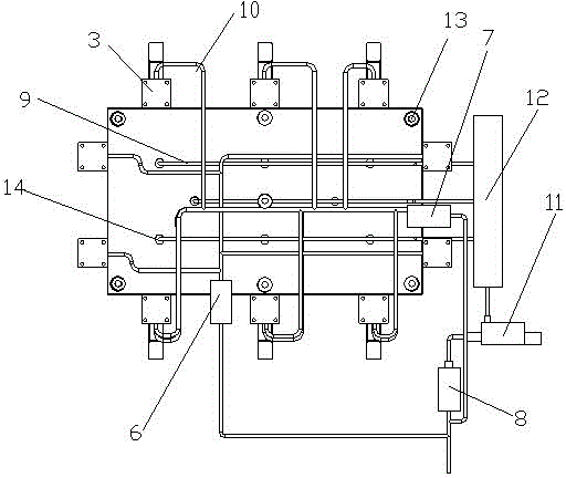
[0031] See figure 1 with image 3 . It should be noted that the structure, ratio, size, etc. shown in the accompanying drawings in this specification are only used to match the content disclosed in the specification for the understanding and reading of those familiar with this technology, and are not intended to limit the implementation of the present invention Limited conditions, so it has no technical significance. Any structural modification, proportional relationship change or size adjustment should still fall under the present invention without affecting the effects and objectives that can be achieved by the present invention. The disclosed technical content must be within the scope of coverage. At the same time, the terms such a...


PUM


Abstract

The invention provides a vacuum suction cup machining clamp and a using method thereof. The vacuum suction cup machining clamp comprises a hollow base, wherein a vacuum adsorption device and a cylinder pipeline are mounted in the base; a smooth supporting plate is arranged on the upper surface of the base; a cross groove is formed in the upper surface of the supporting plate; cylinders are arranged around the supporting plate; a pressing plate is arranged at the upper end of each cylinder and is provided with an extension head end, and each pressing plate is used for pressing the edge of the corresponding supporting plate; air exhaust holes are formed in the supporting plate; supporting columns are arranged between the supporting plate and the base. A to-be-machined product is adsorbed to the clamp by utilizing a vacuum generator and a vacuum adsorption pipe, and the problem that the to-be-machined product deforms due to over-exertion of a conventional clamp is solved; in addition, the edge of the to-be-machined product is kept pressed by the pressing plates, and the problems of displacement and the like in the machining process are avoided.

Description

Technical field [0001] The invention relates to a sucker processing fixture and a use method thereof. Background technique [0002] In the existing machining industry, metal or non-metallic thin-plate parts are particularly processed. Due to the low rigidity of the parts, and the required parts are particularly thin, the clamping force and cutting force of traditional fixtures are used. Under the action of factors such as, cutting vibration, etc., the parts are deformed after processing, which cannot meet the machining accuracy, and the thickness of the plate parts is thin. The existing machine tool fixtures cannot clamp the parts to be processed on the CNC milling machine, and thin parts cannot be realized. Processing. [0003] Generally, flat products processed by machining are fixed by pressing plates, but the products produced by our company need to be cavities and the thickness is too small, which easily deforms the processed products, and the flatness does not meet the requ...

Claims


Application Information

Patent Timeline
IPC IPC(8): B23Q3/08
CPCB23Q3/08B23Q3/065B23Q2703/04
Inventor 朱德平
Owner SUZHOU IND PARK YIDA PRECISION ENG CO LTD
Features
  • Generate Ideas
  • Intellectual Property
  • Life Sciences
  • Materials
  • Tech Scout
  • Unparalleled Data Quality
  • Higher Quality Content
  • 60% Fewer Hallucinations
Learn More