A device that can realize automatic chamfering of optical fiber ferrule

An optical fiber ferrule and ferrule technology, which is applied in grinding/polishing equipment, metal processing equipment, grinding feed motion, etc., can solve the problems of prolonging the processing cycle, affecting the efficiency, and complicated production procedures, so as to improve the production efficiency. , save time, save labor effect

Inactive Publication Date: 2016-10-26
喻崇义
View PDF7 Cites 0 Cited by
  • Summary
  • Abstract
  • Description
  • Claims
  • Application Information

AI Technical Summary

Problems solved by technology

[0002] Optical fiber ferrule is one of the core components of optical fiber communication products. In order to facilitate insertion, the end of the ferrule needs to be chamfered during production. In the prior art, the chamfering processing equipment of the ferrule mostly uses grippers and cylinders. To fix and transport, limited to the structure of the equipment, the number of jaws should not be too much, which limits the number of single processing, resulting in complicated production processes and affecting efficiency; There will be an invalid reset action in one processing, which will prolong the processing cycle and cause a large cumulative error in size

Method used

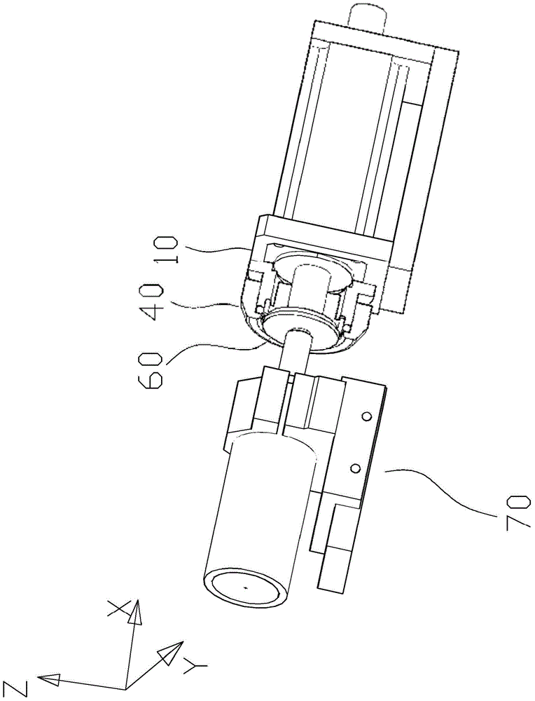
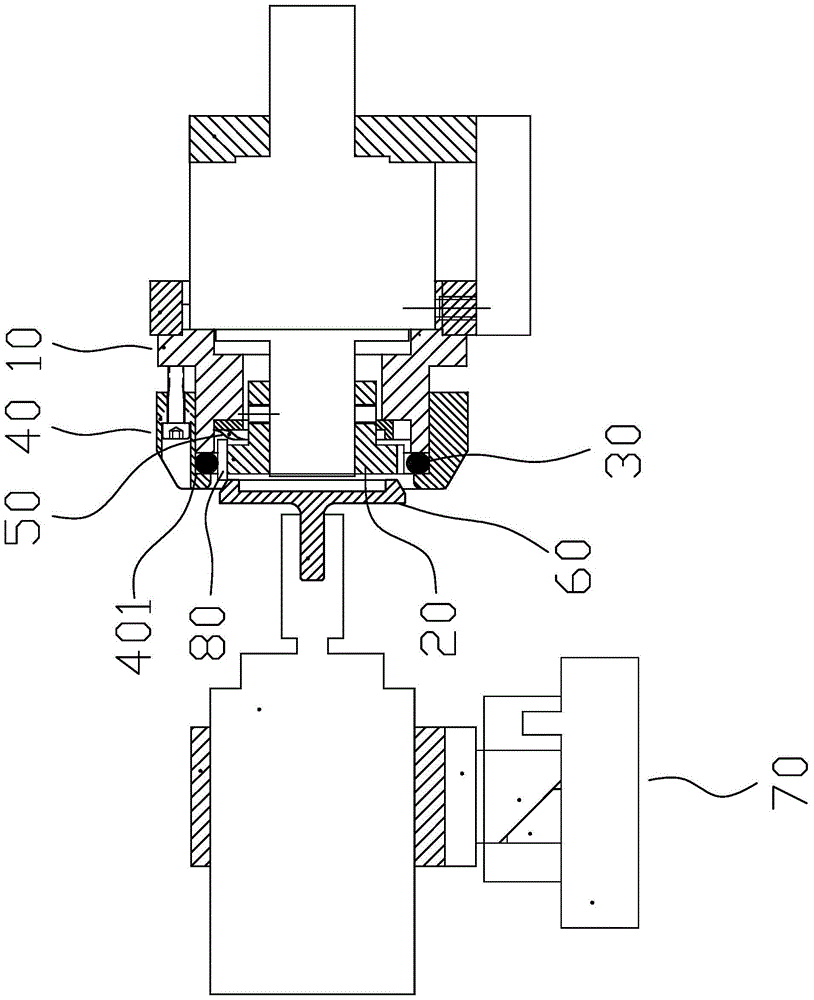
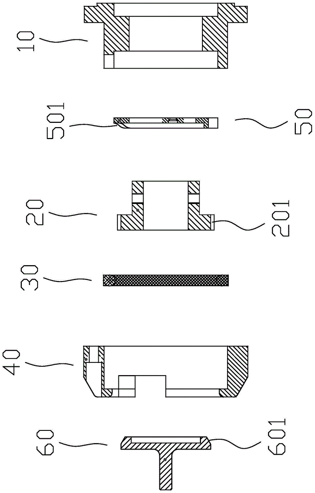

Image

  • A device that can realize automatic chamfering of optical fiber ferrule
  • A device that can realize automatic chamfering of optical fiber ferrule
  • A device that can realize automatic chamfering of optical fiber ferrule

Examples


Embodiment Construction

[0027] The idea, specific structure and technical effects of the present invention will be clearly and completely described below in conjunction with the embodiments and accompanying drawings, so as to fully understand the purpose, scheme and effect of the present invention. It should be noted that, in the case of no conflict, the embodiments in the present application and the features in the embodiments can be combined with each other.

[0028] It should be noted that, unless otherwise specified, when a feature is called "fixed" or "connected" to another feature, it can be directly fixed and connected to another feature, or indirectly fixed and connected to another feature. on a feature. In addition, descriptions such as up, down, left, and right used in the present invention are only relative to the mutual positional relationship of the components of the present invention in the drawings.

[0029] Also, unless defined otherwise, all technical and scientific terms used herei...


PUM


Abstract

The invention discloses automatic chamfering equipment of optical fiber ferrules, comprising a base, a ferrule conveying device, a ferrule limiting device, a feeding device and a chamfering device. The ferrule conveying device is arranged on the base and used for constantly conveying the ferrule. The ferrule limiting device is used with the ferrule conveying device to avoid the ferrule separating from the ferrule conveying device, and accordingly a feeding inlet and a discharging outlet are formed. The feeding device is used for converting movement of the ferrule along with the movement of the ferrule conveying device into feeding displacement for chamfering. The chamfering device is arranged on one side of the ferrule conveying device and used for chamfering the ferrule. The automatic optical fiber ferrule chamfering equipment is easy to operate and automatically runs, thereby saving labor; the ferrule can be continuously chamfered, useless rework, clamping and demounting is avoided, time is greatly shortened, and production efficiency is improved.

Description

technical field [0001] The invention relates to an automatic device, in particular to a device capable of realizing automatic chamfering of optical fiber ferrules. Background technique [0002] Optical fiber ferrule is one of the core components of optical fiber communication products. In order to facilitate insertion, the end of the ferrule needs to be chamfered during production. In the prior art, the chamfering processing equipment of the ferrule mostly uses grippers and cylinders. To fix and transport, limited to the structure of the equipment, the number of jaws should not be too much, which limits the number of single processing, resulting in complicated production processes and affecting efficiency; There will be an invalid reset action in one processing, which will prolong the processing cycle and cause a large accumulation of dimensional errors. Contents of the invention [0003] In order to overcome the deficiencies of the prior art, the present invention provid...

Claims


Application Information

Patent Timeline
Patent Type & Authority Patents(China)
IPC IPC(8): B24B9/06
CPCB24B9/06B24B41/005
Inventor 喻崇义
Owner 喻崇义
Why Eureka
Try Eureka