

Three-dimensional (3D) horizontal well borehole track controlling method
A control method and wellbore trajectory technology, applied in wellbore/well components, directional drilling, earth-moving drilling, etc., can solve the problem of high cost and achieve the effect of low cost, easy construction and easy operation
- Summary
- Abstract
- Description
- Claims
- Application Information
AI Technical Summary
Problems solved by technology
Method used
Image

Examples
Embodiment Construction
[0039] The specific embodiments of the present invention will be further described below in conjunction with the accompanying drawings.
[0040] Taking a three-dimensional horizontal well in Jinghe Oilfield, Ordos Basin as an example, the specific implementation process of the method for controlling the wellbore trajectory of the three-dimensional horizontal well of the present invention will be described in detail below. This well adopts ZJ40 Roman drilling rig, adopts conventional "screw drilling tool + MWD measurement system", selects F-1300 drilling pump, and is not equipped with top drive.
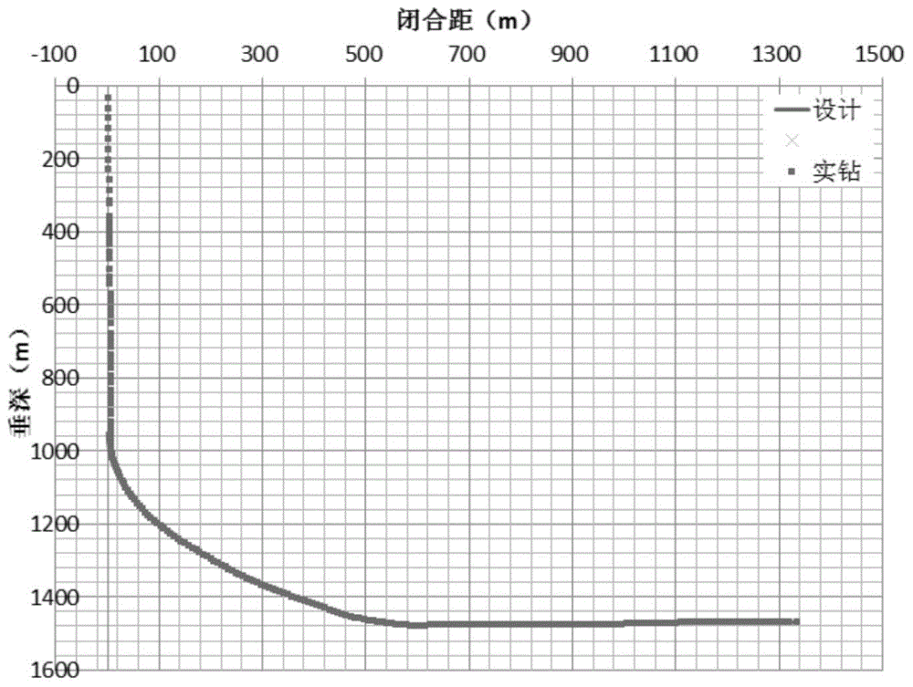
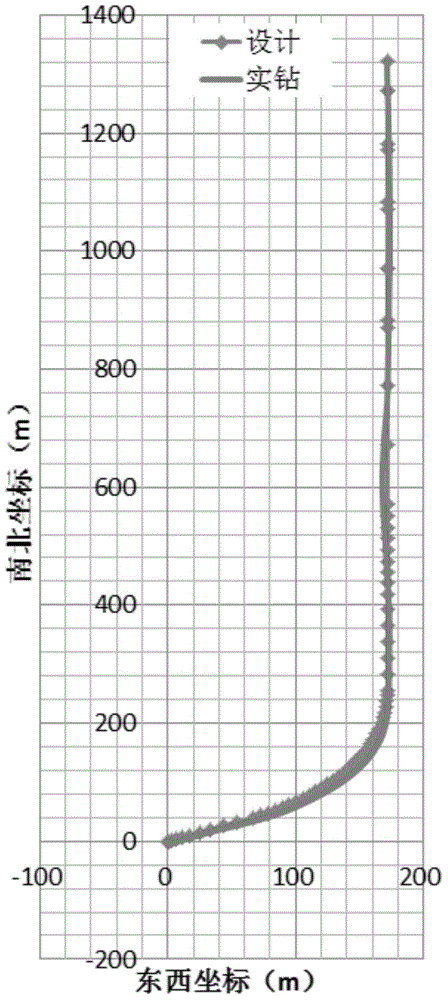
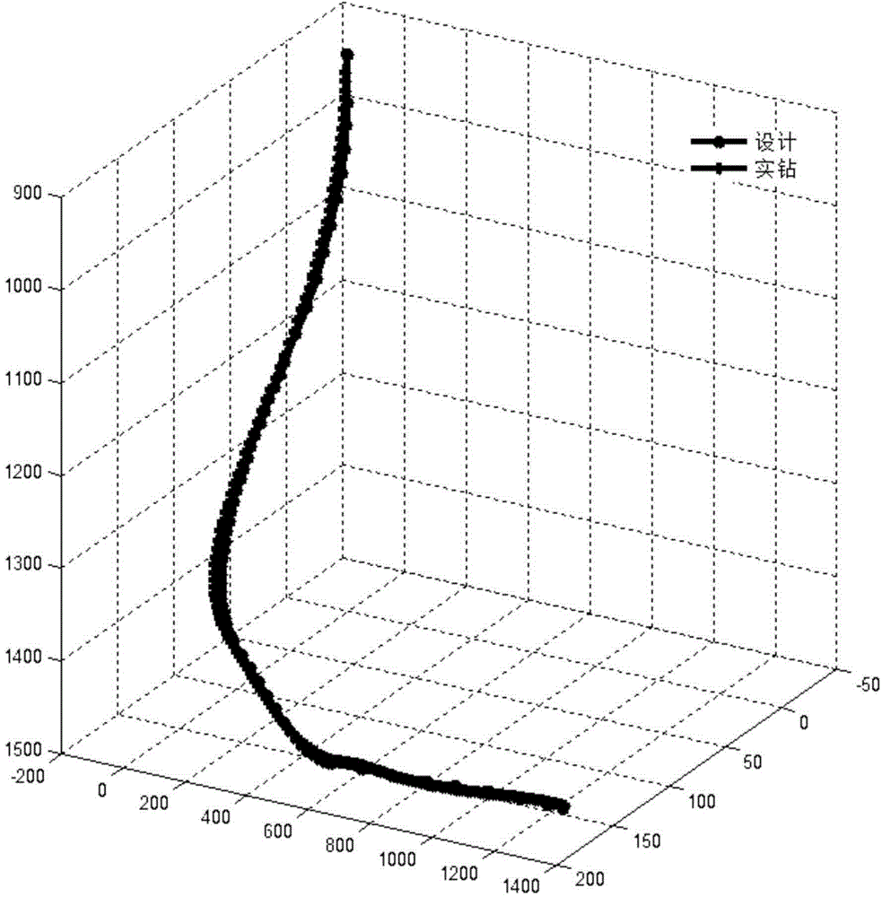
[0041] 1. Carry out drilling engineering design for horizontal wells according to drilling geological design. This embodiment adopts six-section wellbore trajectory, including one-dimensional vertical section, two-dimensional inclination section, three-dimensional well section, two-dimensional stabilizing section, two-dimensional inclination section and two-dimensional horizontal sect...
PUM
 Abstract
Description
Claims
Application Information