Car-mounted hydrogen generation system

A hydrogen generation technology, applied in the charging system, engine components, combustion engines, etc., can solve the problems of affecting processing and combustion, prone to failure, safety hazards, etc., to reduce moisture, reduce processing pressure, and change cooling efficiency. Effect

Inactive Publication Date: 2015-04-01
BEIJING UNIV OF TECH
View PDF1 Cites 2 Cited by
  • Summary
  • Abstract
  • Description
  • Claims
  • Application Information

AI Technical Summary

Problems solved by technology

However, due to technical limitations, hydrogen is usually used to pass through a large amount of chemicals and other materials, and waste water and waste are discharged. These are polluted, and due to the large amount of storage during use or transportation, there are serious accidents. Hidden danger, in order to solve this problem, Chinese patent CN203161381U discloses a vehicle-mounted hydrogen generating device, including a car equipped with an air filter and an electric door lock, and a liquid storage room mixed with an aqueous solution of electrolyte; An electrolyzer for electrolyzing the aqueous solution in the room to generate hydrogen; a cooling chamber for cooling the generated hydrogen, which is connected to the liquid storage chamber through pipelines, and a power supply for the electrolyzer; the cooling chamber is equipped with The air outlet connected to the air filter, the hydrogen produced by the utility model passes into the car air filter, which can increase the power of the car for the mixed combustion of carburetion gas and gasoline, and can save more than 20% of the fuel when driving on low-speed highways Exercising on the road can save more than 30% of oil; however, this utility model adopts an aqueous solution cooling method for the hydrogen generated by electrolysis, which increases the moisture in the hydrogen and adds a lot of pressure to the isolator to deal with the moisture in the hydrogen , it is prone to failure, and the direct cooling effect of the aqueous solution is also very poor. After long-term operation, the cooling effect of hydrogen will drop sharply, which will affect the post-processing and combustion. It is also a big safety hazard for the car body itself.

Method used


Image

  • Car-mounted hydrogen generation system

Examples


Embodiment Construction

[0013] The technical solutions of the present invention will be further described in detail below in conjunction with specific embodiments.

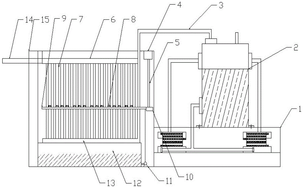
[0014] see figure 1 , a vehicle-mounted hydrogen generation system, including a liquid storage chamber 1 with an electrolytic aqueous solution built in, an electrolyzer 2 for electrolyzing the aqueous solution in the above-mentioned liquid storage chamber 1 to generate hydrogen, and a heat exchanger for cooling the generated hydrogen Device 14; the electrolysis machine 2 is connected with a DC power supply, the positive pole of the DC power supply is connected to the positive pole of the electrolysis machine 2 through a breaker, and the negative pole is connected to the negative pole of the electrolysis machine 2, and the breaker is connected to the electric door lock of the car through a relay Connected and disconnected or closed under the control of the electric door lock of the car; the electrolysis machine 2 forms a circulation with ...


PUM


Abstract

The invention discloses a car-mounted hydrogen generation system and relates to the field of car energy development. The system comprises solution storage chamber containing electrolysis solutions, an electrolysis machine for electrolyzing the electrolysis solutions in the solution storage chamber to generate hydrogen and a heat exchanger for cooling the generated hydrogen. The electrolysis machine is connected with a direct-current power supply. The heat exchanger is the all aluminum cooling-fin-free micro-channel heat exchanger. A water collection tank is arranged below the heat exchanger, and a water pump is arranged on one side of the water collection tank and is connected between the water collection tank and a spray water unit. Compared with the prior art, a few of electrolysis solutions are added in water in the solution storage chamber, electrolysis is performed through the electrolysis machine to generate hydrogen, the electrolyzed hydrogen is cooled through the water-film external heat exchanger, moisture mixed in hydrogen is reduced during cooling, and treatment pressure of later car air filters is reduced.

Description

technical field [0001] The invention relates to the field of automobile energy development, in particular to a vehicle-mounted hydrogen generation system. Background technique [0002] Nowadays, gasoline is usually used to provide power for automobiles, but due to excessive exploitation and utilization of oil, serious environmental pollution has been caused. At the same time, the price of gasoline has been rising due to the reduction of the quantity, which has brought huge economic pressure to car owners. As a clean energy source, hydrogen has a combustion value much higher than that of gasoline. However, due to technical limitations, hydrogen is usually used to pass through a large amount of chemicals and other materials, and waste water and waste are discharged. These are polluted, and due to the large amount of storage during use or transportation, there are serious accidents. Hidden danger, in order to solve this problem, Chinese patent CN203161381U discloses a vehicle-...

Claims


Application Information

Patent Timeline
Patent Type & Authority Applications(China)
IPC IPC(8): F02M25/12C25B1/04
CPCY02E60/36Y02T10/12
Inventor 纪常伟冯雨汪硕峰张擘苏腾
Owner BEIJING UNIV OF TECH
Why Eureka
Try Eureka