Combined valve

A combined valve and ball valve technology, applied in the field of combined valves, can solve problems such as poor working conditions, and achieve the effects of fewer leakage points, increased switch life, and convenient operation.

Inactive Publication Date: 2015-04-01
BEIJING OTE CONTROL VALVE
View PDF6 Cites 6 Cited by
  • Summary
  • Abstract
  • Description
  • Claims
  • Application Information

AI Technical Summary

Problems solved by technology

[0004] The invention provides a combination valve, which solves the problem of valves with bad working conditions and requiring long-term no leakage

Method used


Image

  • Combined valve

Examples


Embodiment Construction

[0031] The following clearly and completely describes the technical solutions in the embodiments of the present invention. Obviously, the described embodiments are only some of the embodiments of the present invention, but not all of them. Based on the embodiments of the present invention, all other embodiments obtained by persons of ordinary skill in the art without making creative efforts belong to the protection scope of the present invention.

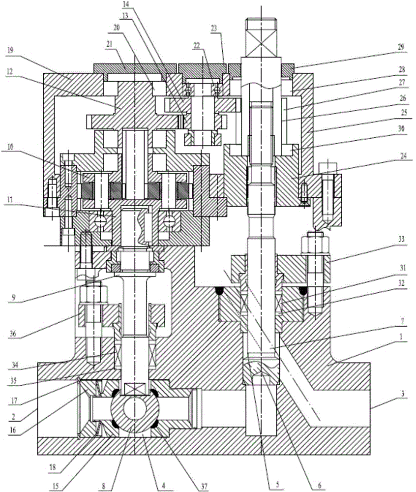
[0032] Such as figure 1 As shown, this embodiment provides a combination valve, including a combination valve body 1, one side of the combination valve body 1 is provided with a medium inlet 2 and a ball valve chamber 4 communicating with the medium inlet 2, and the other side of the combination valve body 1 is provided with a The medium outlet 3 communicates with the shut-off valve chamber 5 connected with the medium outlet 3, the ball valve chamber 4 communicates with the shut-off valve chamber 5, the shut-off valve core 6 arrange...


PUM


Abstract

The invention provides a combined valve. The combined valve can be free of leakage for a long time under severe working conditions. The combined valve comprises a combined valve body, wherein a medium inlet and a ball valve cavity communicated with the medium inlet are formed in one side of the combined valve body, a medium outlet and a stop valve cavity communicated with the medium outlet are formed in the other side of the combined valve body, the ball valve cavity is communicated with the stop valve cavity, a stop valve element arranged in the stop valve cavity a is connected with stop valve rod, a handle is connected to one end of the stop valve rod, a ball valve ball body arranged in the ball valve cavity is connected with a ball valve rod, the ball valve rod is connected with an output shaft at one end of a speed reduction mechanism, the other end of the speed reduction mechanism is connected with a driving gear for driving the speed reduction mechanism to rotate, the driving gear is meshed with a transition gear, and the stop valve rod drives the transition gear to rotate. The combined valve is integrally designed, has few leakage points, and is more reliable in pipeline installation, and more convenient to operate.

Description

technical field [0001] The invention relates to the field of valves, in particular to a combined valve. Background technique [0002] A valve is a device used to control the direction, pressure, and flow of a fluid in a fluid system. It can make or stop the medium in the piping and equipment, and can control its flow. Usually, there are stop valves, plug valves, ball valves, butterfly valves, Needle valves, diaphragm valves, etc. [0003] During the operation of thermal power plants, there is high temperature everywhere. Under severe working conditions such as high pressure, the leakage of any valve will cause great losses to the power plant, especially the leakage of external exhaust valves. For example: main steam relief valve, drain door, blowdown door, etc. Contents of the invention [0004] The invention provides a combined valve, which solves the valve problem of bad working conditions and requiring long-term no leakage. [0005] Technical scheme of the present i...

Claims


Application Information

Patent Timeline
Patent Type & Authority Applications(China)
IPC IPC(8): F16K13/00F16K31/53F16K41/02F16K1/32F16K5/08F16H57/02
CPCF16K13/00F16H57/02F16K1/02F16K1/32F16K5/0657F16K5/0684F16K5/0694F16K5/08F16K31/563F16K41/02
Inventor 徐海涛
Owner BEIJING OTE CONTROL VALVE
Why Eureka
Try Eureka