

Wire integration type lighting lamp box
A lighting light box, integrated technology, applied in lighting devices, fixed lighting devices, lighting and heating equipment, etc., can solve the problems of reducing linear light source wiring, increasing connection points, connection failure, etc., to reduce aging and connection stability, Facilitate adhesive installation and improve the effect of scattering performance
- Summary
- Abstract
- Description
- Claims
- Application Information
AI Technical Summary
Problems solved by technology
Method used
Image

Examples
Embodiment 1
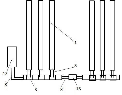
[0027] Example 1, see figure 1 As shown, the wire-integrated lighting light box of the present invention is composed of a box, and the volume surrounded by the box surrounds a planar light emitting device. The planar light emitting device includes an LED straight strip light 1, a connecting device and a fixing device, and the fixing device includes a card slot 2 and the terminal board fixing groove 3, the connection device includes wires 8, connecting terminals 9 and terminal board 10, the terminal board fixing groove 3 is embedded in the deck groove 2, the connecting terminal 9 is connected to the wire 8, and the wire 8 is connected to the LED strip light 1, and connected The terminal 9 is fixed on the surface of the terminal board 10 , the socket groove 2 is fixedly connected to the side wall 13 of the box body, and the terminal board 10 is slidably embedded in the terminal board fixing groove 3 . The terminal boards 10 are connected to power adapters 12 , and the adjacent t...
Embodiment 2
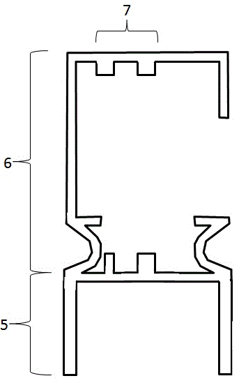
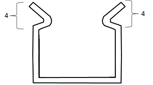
[0028] Example 2, see Figure 2 to Figure 4 As shown, the wire-integrated lighting light box of the present invention is composed of a box, and the volume surrounded by the box surrounds a planar light emitting device. The planar light emitting device includes an LED straight strip light 1, a connecting device and a fixing device. From the cross section of the fixing device Look, the deck slot 2 is open on one side, and there are two symmetrical protrusions 4 on the edge of the opening of the deck slot 2. The volume of the terminal board fixing groove 3 includes a card slot cavity 5 and a terminal board cavity 6, there is a side wall between the card slot cavity 5 and the terminal board cavity 6, and the side wall of the terminal board cavity 6 has two The opposite terminal board 10 card slot 7, the terminal board cavity 6 has an opening, the card slot cavity 5 is seamlessly and slidably embedded in the card slot 2, the terminal board 10 is inserted and fixed in the terminal b...
Embodiment 3
[0029] Example 3, see Figure 5 with Image 6 As shown, the surface of the terminal board 10 in the embodiment has a metal elastic piece 15 , and the metal elastic piece 15 connects the wire and the terminal board cavity 6 . There is an insulating pad 11 at the connection portion between the deck groove 2 and the box side wall 13 to realize the insulating connection between the deck slot 2 and the box side wall 13 .
PUM
| Property | Measurement | Unit |
|---|---|---|
| Size | aaaaa | aaaaa |
| Size | aaaaa | aaaaa |
Abstract
Description
Claims
Application Information