Eureka AIR delivers breakthrough ideas for toughest innovation challenges, trusted by R&D personnel around the world.

Gas cooker capable of continuously regulating firepower

A technology of gas cooker and firepower, which is applied in valve details, heating fuel, home appliances, etc. It can solve the problems of increasing product cost, few firepower adjustment gears, and energy waste, so as to improve heating efficiency, flexibly adjust and prevent wasteful effect

Inactive Publication Date: 2015-04-01
谢启标
View PDF9 Cites 15 Cited by
  • Summary
  • Abstract
  • Description
  • Claims
  • Application Information

AI Technical Summary

Problems solved by technology

However, the burners in the existing gas cookers usually have inner nozzles and outer nozzles, and the current gas cookers usually only use a solenoid valve to control the gas flow of a single nozzle or two nozzles at the same time, so that the two The flames of two nozzles have the same size, and the number of gears for firepower adjustment is less, and when the object to be heated is smaller than the size of the outer ring nozzle, the flame of the outer ring nozzle cannot play a heating role, resulting in energy waste; and because the outer ring The nozzle is larger than the inner ring nozzle, and the gas flow required for the same flame size is more than that of the inner ring, and the size of each gas outlet of most solenoid valves is the same, so the gas flow supplied to the inner ring nozzle and the outer ring nozzle Just the same, when the firepower is high, the gas in the inner ring nozzle cannot be completely burned, wasting gas resources, customizing solenoid valves with different gas outlet sizes will increase the cost of the product, and it is not conducive to maintenance and replacement when the solenoid valve fails

Method used


Image

  • Gas cooker capable of continuously regulating firepower
  • Gas cooker capable of continuously regulating firepower
  • Gas cooker capable of continuously regulating firepower

Examples


Embodiment Construction

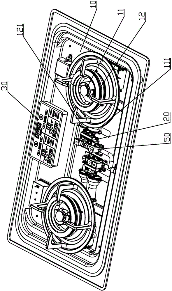
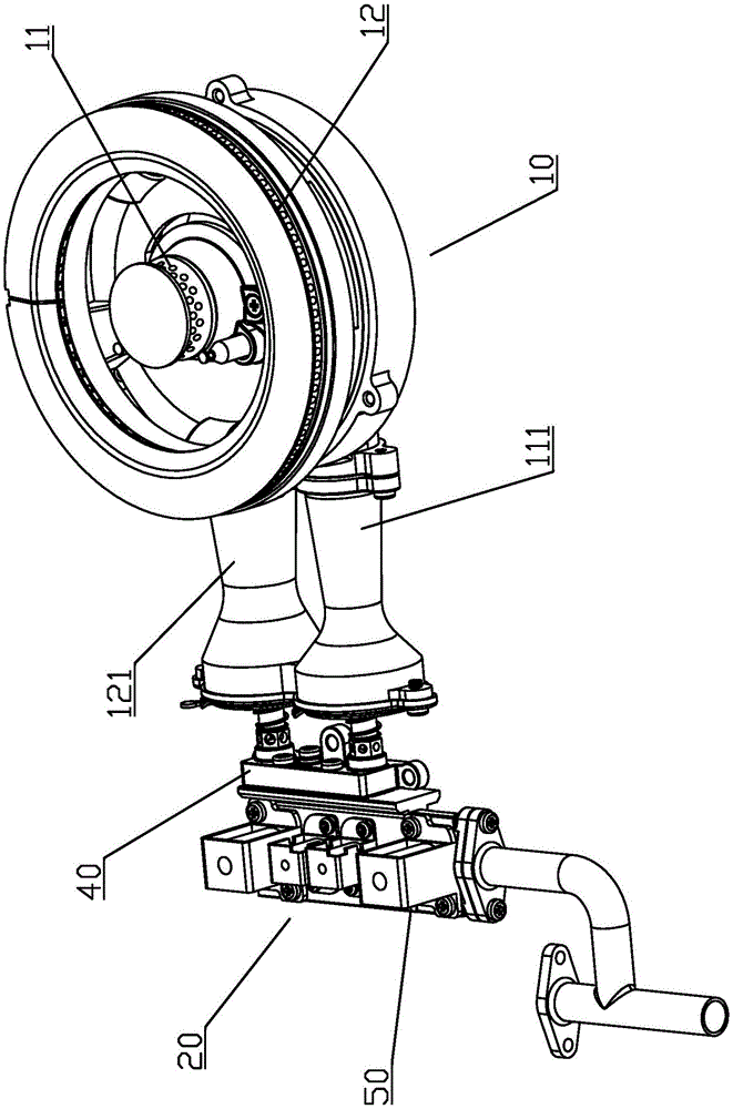
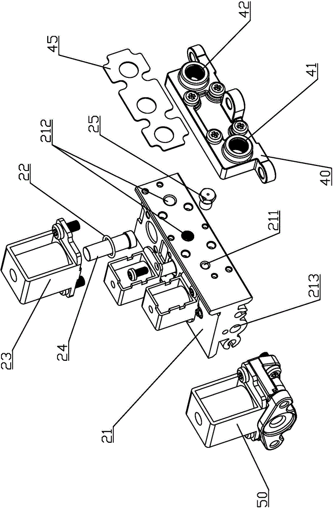
[0017] refer to Figure 1 to Figure 4 , a gas cooker that can continuously adjust the firepower, including a burner 10, a solenoid valve 20, a solenoid master valve 50 and a controller 30, the burner 10 includes an inner ring nozzle 11 that communicates with the solenoid valve 20 through an inner ring gas delivery pipe 111 And the outer ring nozzle 12 communicated with the solenoid valve 20 through the outer ring gas pipeline 121, the inner ring nozzle 11 is smaller than the outer ring nozzle 12 and is located at the center of the outer ring nozzle 12, the main gas valve is arranged at the inlet of the gas source and the solenoid valve 20 Between the gas ports 213, the solenoid master valve 50 can control the total amount of gas entering the solenoid valve 20, and at the same time can play the role of a safety switch to ensure safe use. The access between the valves 20 is convenient for maintenance.

[0018] The solenoid valve 20 includes a valve body 21, the valve body 21 is...


PUM


Abstract

The invention discloses a gas cooker capable of continuously regulating firepower. The gas cooker comprises a combustor, an electromagnetic valve used for controlling the flow of fuel entering the combustor, and a controller used for controlling the electromagnetic valve, wherein the combustor comprises an inner-ring nozzle and an outer-ring nozzle, the electromagnetic valve comprises a valve body, a fuel inlet and a plurality of gas outlets communicated with the gas inlet respectively are formed in the valve body, the gas outlets comprise an inner-ring gas outlet communicated with the inner-ring nozzle and a plurality of gas outlets which can be simultaneously communicated with the outer-ring nozzle, all the gas outlets are respectively internally provided with valve cores which can be used for controlling opening / closing of the gas outlets and / or the opening degree, and a plurality of electromagnets capable of singly controlling the valve cores to independently act are arranged correspondingly on the valve body. The gas cooker is capable of flexibly regulating the firepower so as to adapt to different demands, can prevent the fuel in the inner-ring nozzle from being wasted, caused by incomplete combustion due to overlarge flow, and has the convenient and energy-saving effects.

Description

technical field [0001] The invention relates to a gas cooker, in particular to a gas cooker which can continuously adjust the firepower. Background technique [0002] Gas cookers are widely used in people's daily life. In recent years, more and more gas cookers have begun to use solenoid valves to control the gas flow and then the firepower, which greatly facilitates the use of gas cookers. However, the burners in the existing gas cookers usually have inner nozzles and outer nozzles, and the current gas cookers usually only use a solenoid valve to control the gas flow of a single nozzle or two nozzles at the same time, so that the two The flames of two nozzles have the same size, and the number of gears for firepower adjustment is less, and when the object to be heated is smaller than the size of the outer ring nozzle, the flame of the outer ring nozzle cannot play a heating role, resulting in energy waste; and because the outer ring The nozzle is larger than the inner ring...

Claims


Application Information

Patent Timeline
Patent Type & Authority Applications(China)
IPC IPC(8): F24C3/12F16K31/06
CPCF24C3/126F16K11/22F16K31/0603
Inventor 谢启标
Owner 谢启标
Why Eureka
Eureka Blog
Learn More