All-fiber mode converter and light system
A mode converter, all-fiber technology, applied in optical waveguides, light guides, optics, etc., can solve problems such as inability to achieve mode coupling, achieve high conversion efficiency, low conversion noise, and achieve simple effects
- Summary
- Abstract
- Description
- Claims
- Application Information
AI Technical Summary
Problems solved by technology
Method used
Image

Examples
Embodiment Construction
[0047] The present invention will be further described in conjunction with the accompanying drawings.
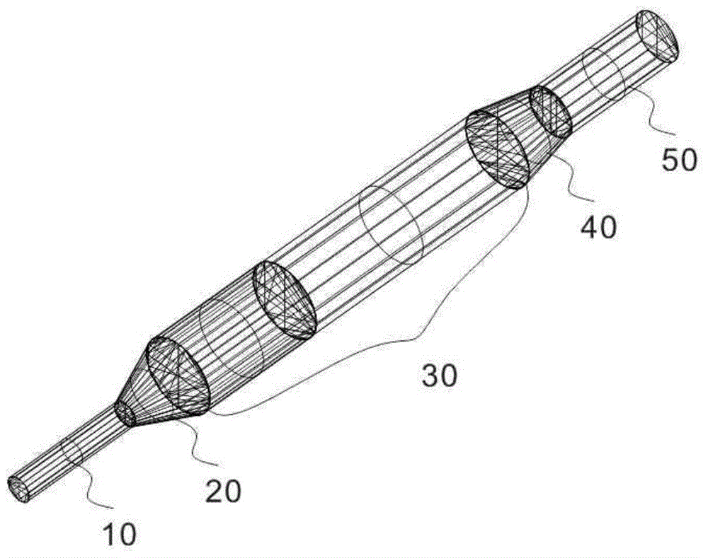
[0048] Such as figure 1 As shown, the optical system of the all-fiber mode converter of the present invention includes an input fiber 10, two mode field matchers (20, 40), an all-fiber mode converter (30), an output fiber (50), and an input fiber (10 ), the first mode field matcher (20), the all-fiber mode converter (30), the second mode field matcher (40), and the output fiber (50) are welded together in sequence to achieve the purpose of mode conversion. The first propagation mode is transmitted to the all-fiber mode converter (30) with the lowest loss through the first mode field matcher (20) from the input fiber 10, and only the first fiber mode converter (30) exists in the fiber after passing through the all-fiber mode converter (30). The two propagation modes are then passed through the second mode field matcher (40) to transmit the second propagation mode to the outp...
PUM
| Property | Measurement | Unit |
|---|---|---|
| Core diameter | aaaaa | aaaaa |
| Length | aaaaa | aaaaa |
Abstract
Description
Claims
Application Information
 - R&D
- Intellectual Property
- Life Sciences
- Materials
- Tech Scout
- Unparalleled Data Quality
- Higher Quality Content
- 60% Fewer Hallucinations
Browse by: Latest US Patents, China's latest patents, Technical Efficacy Thesaurus, Application Domain, Technology Topic, Popular Technical Reports.
© 2025 PatSnap. All rights reserved.Legal|Privacy policy|Modern Slavery Act Transparency Statement|Sitemap|About US| Contact US: help@patsnap.com