
ARM-based ventilator equipment detection remote monitoring system and method

A remote monitoring system and equipment detection technology, applied in general control systems, control/regulation systems, program control, etc., can solve problems affecting exhaust gas efficiency, system stability, and reduced monitoring reliability, and achieve data sharing , strong reliability, and strong real-time processing capabilities

Active Publication Date: 2015-04-01
CETC NINGBO MARINE ELECTRONICS RES INST
View PDF5 Cites 7 Cited by
  • Summary
  • Abstract
  • Description
  • Claims
  • Application Information

AI Technical Summary

Problems solved by technology

[0002] In the environmental purification monitoring system, the ventilator plays a very important role in introducing fresh air and removing harmful gas and dust, but long-term and uninterrupted use will cause the ventilator to block and other faults, and the fan is not cleaned in time , will affect the efficiency of exhaust gas and affect the work progress
[0003] However, the existing fan monitoring and control methods mostly use smart instruments to measure data, which requires manual inspections on a regular basis, which makes the real-time performance worse, and the monitoring points are scattered, wasting manpower, material resources and financial resources
The method of using data acquisition card or PLC to obtain monitoring data, and then connecting to the host computer through the network to display is high in equipment cost, troublesome in wiring, and requires line maintenance. The stability of the system is greatly affected, and the reliability of monitoring is also reduced a lot. , once a problem occurs, it cannot realize human-computer interaction with the control system in real time, let alone determine the operation strategy after the fault occurs in the first place

Method used


Image

  • ARM-based ventilator equipment detection remote monitoring system and method
  • ARM-based ventilator equipment detection remote monitoring system and method
  • ARM-based ventilator equipment detection remote monitoring system and method

Examples


Embodiment Construction

[0042] The present invention will be further described in detail below in conjunction with the examples, which do not limit the present invention.

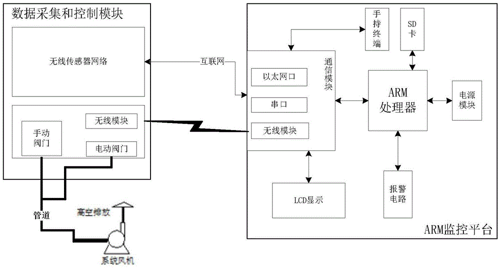
[0043] System embodiment: like figure 1 As shown, the ARM-based ventilator equipment detection remote monitoring system provided by this system embodiment is composed of two parts, namely the front-end data acquisition and control module, and the back-end ARM monitoring platform;

[0044] The data acquisition and control module of the front end includes:

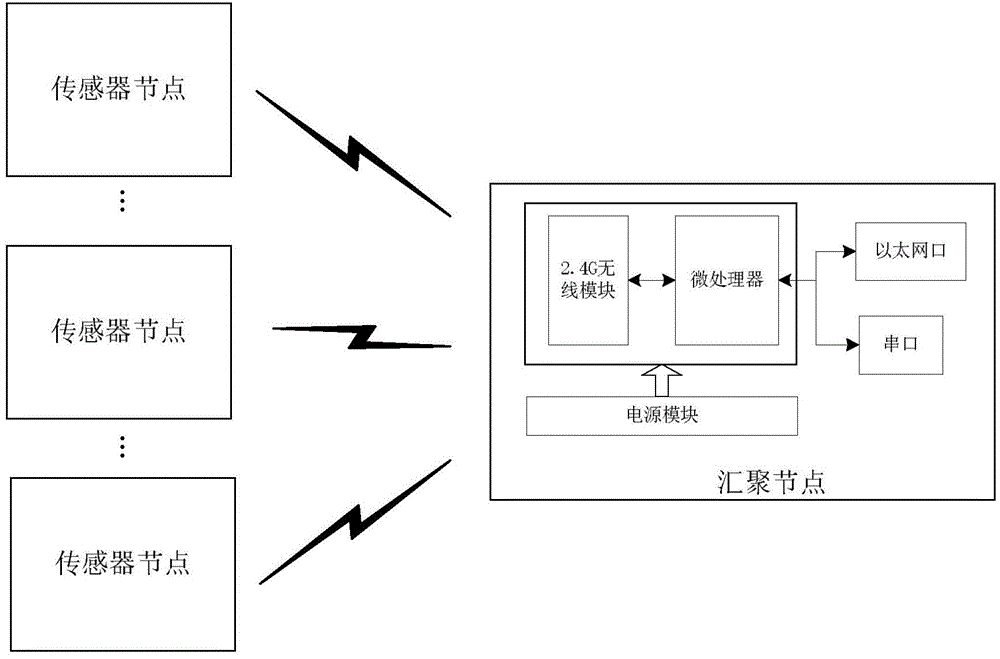
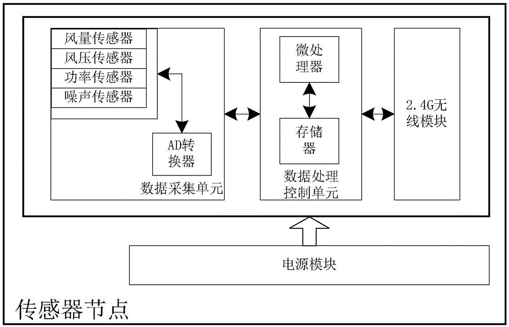
[0045] wireless sensor networks such as figure 2 As shown, it includes a sensor node for collecting data parameters of the working state of the fan, and a converging node for data transmission between several (ie, one or more) sensor nodes and the ARM monitoring platform, and sensor node task management;

[0046] Valve control module, including manual valves, electric valves that automatically control the exhaust air volume according to the signals sent by the ARM monitorin...


PUM


Abstract

The invention discloses an ARM-based ventilator equipment detection remote monitoring system and method. According to the ARM-based ventilator equipment detection remote monitoring system, a wireless sensor network is responsible for data acquisition and transmission; a valve control module controls the exhaust air rate of an entrance pipeline and the working state of a ventilator; an ARM-based monitoring platform is responsible for data display and processing as well as remote control; when detecting data anomalies, the monitoring platform can wirelessly and remotely control an electric valve to automatically control pipeline output exhaust air rate, can further start a self-cleaning device to perform cleaning, and therefore, intelligent remote monitoring of the working condition of the ventilator can be realized; an alarm circuit can be driven, so that a wireless connection with a mobile handheld device can be established, and therefore, the owner of the mobile handheld device can know the working condition of the ventilator in real time; manual adjustment can be realized through a manual valve; since an electric and manual valve double-control complementary mode is realized, timely failure handling can be benefitted; and therefore, on the whole, efficiency can be improved, usability and compatibility can be also improved, and the stability and reliability of the system can be ensured.

Description

technical field [0001] The invention relates to real-time monitoring and control of the running state of a ventilator, and belongs to the field of equipment detection and monitoring. Background technique [0002] In the environmental purification monitoring system, the ventilator plays a very important role in introducing fresh air and removing harmful gas and dust, but long-term and uninterrupted use will cause the ventilator to block and other faults, and the fan is not cleaned in time , will affect the efficiency of exhaust gas and affect the progress of work. [0003] However, the existing fan monitoring and control methods mostly use smart instruments to measure data, which requires manual regular inspections, which makes the real-time performance worse, and the monitoring points are scattered, which wastes manpower, material resources and financial resources. The method of using data acquisition card or PLC to obtain monitoring data, and then connecting to the host co...

Claims


Application Information

Patent Timeline
IPC IPC(8): G05B19/418
CPCY02P90/02G05B19/042G05B2219/25314
Inventor 李垣江卞建秀张迪明
Owner CETC NINGBO MARINE ELECTRONICS RES INST
Learn More