A Transient Dynamics Analysis Method for Solar Sails to Determine Effective Propulsion Acceleration Breakdown

A technology of dynamic analysis and acceleration, applied in the field of transient dynamic analysis of solar sails, can solve problems such as large calculation errors of non-time-varying light pressure models, failure to consider time-varying effects of light pressure, missing multiplication, etc.

Inactive Publication Date: 2017-07-28
CHINA ACADEMY OF SPACE TECHNOLOGY
View PDF3 Cites 0 Cited by
  • Summary
  • Abstract
  • Description
  • Claims
  • Application Information

AI Technical Summary

Problems solved by technology

[0004] However, solar sail researchers at home and abroad usually do not consider the time-varying effect of light pressure when calculating the transient effective propulsion acceleration
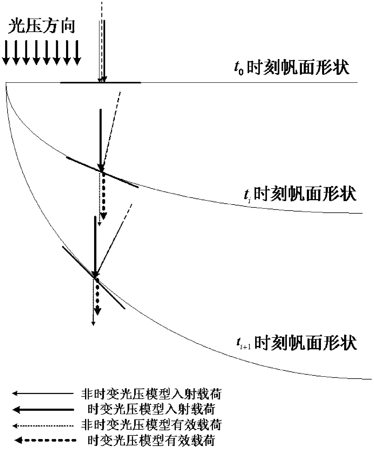
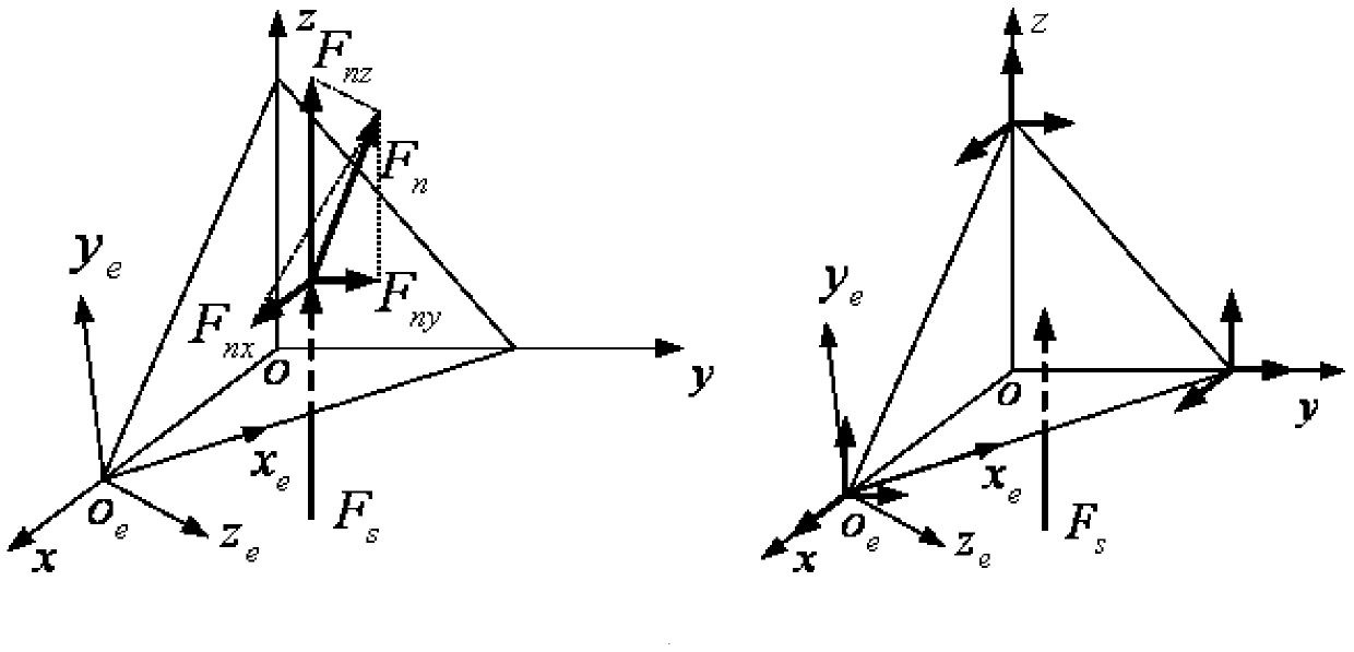
like figure 2 and image 3 As shown, the non-ideal plane of the initial state of the traditional solar sail surface and the two factors of the deformation of the sail surface during operation, the incident load of the time-invariant photopressure model is always perpendicular to the micro-element of the sail surface (thin solid line ), but the direction of the incident light pressure in the actual light pressure model remains unchanged (thick solid line), which will miss the direction cosine of the angle between the micro-element and the direction of the light pressure once in the final calculation of the effective advancing light pressure, resulting in The final calculated effective propulsion load (thin dotted line) is slightly higher than the real time-varying case (thick dotted line), and it can be noticed that the greater the deformation of the sail surface, the greater the calculation error of the time-invariant light pressure model

Method used


Image

  • A Transient Dynamics Analysis Method for Solar Sails to Determine Effective Propulsion Acceleration Breakdown
  • A Transient Dynamics Analysis Method for Solar Sails to Determine Effective Propulsion Acceleration Breakdown
  • A Transient Dynamics Analysis Method for Solar Sails to Determine Effective Propulsion Acceleration Breakdown

Examples


Embodiment

[0067] Example: Static finite element simulation analysis of 160m solar sail structure

[0068] 1) Establish the finite element model of the solar sail, as shown in 4, mainly including: respectively establish the model of the one-dimensional beam element of the support arm and the two-dimensional triangular shell element of the sail surface, set the side length of the square sail to 160m, and set the mass of the central body to m center =100kg, terminal weight m vertex =12.4kg, center body moment of inertia J center =0kg·m 2 , the outer diameter of the support arm D = 300mm, the wall thickness b = 0.1mm, the thickness of the sail surface h = 1.5μm; set the material property E of the support arm beam =210GPa, γ beam =0.33, ρ beam =848kg / m 3 , material property E of the sail surface film sail =2.5GPa, γ sail =0.34, ρ sail =1420kg / m 3 ;Set the direction of prestress as the two normal stresses in the sail surface, the size is 50000Pa; set the initial solution time t 0 = ...


PUM


Abstract

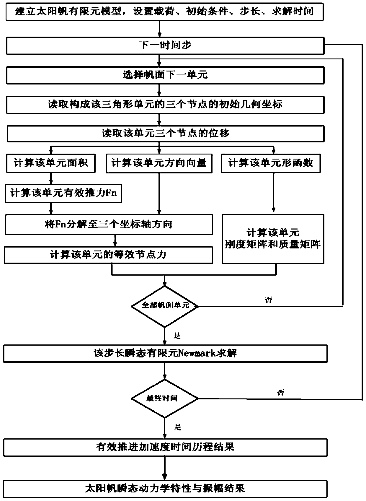
The invention discloses a solar sail transient dynamic analyzing method for determining effective propulsion acceleration breakage. The solar sail transient dynamic analyzing method comprises the following steps: (1) establishing a solar sail finite element model; (2) entering the n-th solving moment and starting t from the t0+delta t; (3) calculating the rigidity matrix and the mass matrix of each sail area unit at the t moment under pre-stress according to the included angle of each sail area unit and the light pressure direction moment, thereby obtaining load of the area subjected to the light pressure of each sail area unit; (4) obtaining a global stiffness matrix Kt containing p units and the load row vector Ft as well as global mass m and the global mass matrix Mt; (5) calculating the final displacement, the final speed and the final acceleration of the t-th moment according to the final displacement, the final speed, the final acceleration at the (t-delta)-th moment, namely the initial conditions of the t-th moment as well as the global rigidity matrix and the load row vector at the t-th moment as well as the global mass matrix; (6) repeating steps (3)-(5) at the (t+delta t)-th moment until the final solving time tn; and (7) obtaining the breakage of the acceleration according to the results.

Description

technical field [0001] The invention relates to a method for analyzing the transient dynamics of a solar sail based on an accurate time-varying light pressure model for determining effective propulsion acceleration damage, and is especially suitable for various types of solar sails with wrinkles that cannot measure surface accuracy and that are in different orbits and attitudes. The precise effective acceleration analysis of a large super-compliant solar sail structure is determined. Background technique [0002] The solar sail is an advanced long-term orbiting spacecraft without propellants. Since it only uses the reflected light pressure of the sun on a large-area film to provide flight power, the solar sail spacecraft can continue to flow wherever sunlight exists. Gain power, and finally achieve speeds that ordinary spacecraft cannot achieve. Because solar sails are not bound by fuel and can run in space for a long time, they are especially suitable for deep space explor...

Claims


Application Information

Patent Timeline
Patent Type & Authority Patents(China)
IPC IPC(8): G06F17/50
CPCY02E60/00
Inventor 杨辰刘宇飞张兴华王立侯欣宾
Owner CHINA ACADEMY OF SPACE TECHNOLOGY
Why Eureka
Try Eureka