Indoor user-defined decoration rendering method based on cloud computing

A custom, cloud computing technology, applied in the field of indoor custom decoration rendering based on cloud computing, can solve the problems of less content, limited computing power of the local computer, heavy load, etc., and achieve the effect of reducing waste

Inactive Publication Date: 2015-04-01
FUJIAN NARKII INFORMATION TECH
View PDF5 Cites 16 Cited by
  • Summary
  • Abstract
  • Description
  • Claims
  • Application Information

AI Technical Summary

Problems solved by technology

[0002] The current interior decoration of buildings wants to see the effect after decoration. Whether it is a rendering or an animation, it has to go through heavy modeling, calculation and rendering to see the final effect. In this process, it takes many times of communication to understand the customer's ideas. , and in the past, the creation of models, data storage, and model rendering were all implemented on the local computer, so there were the following problems: 1. The rendering of the model required a heavy calculation process, and the computing power of the local computer was limited. Therefore, the rendering of the entire model takes a long time and requires high computer performance.
2. Store a large amount of data in the local computer, which will also cause a waste of local computer resources
However, the above method needs to generate a binary snapshot file from the 3D model of the decoration target, and in the actual implementation, it must first apply for a memory space of the same size as the original OBJ file in the local computer. Although the loading speed is improved, it also causes local problems. A waste of computer resources; moreover, the above method is to display the target material selected by the user on the target component and / or target position according to the recalculated material specification and material extension. Multiple requirements (such as room separation, material replacement of decorative parts, etc.)

Method used


Image

  • Indoor user-defined decoration rendering method based on cloud computing

Examples


Embodiment Construction

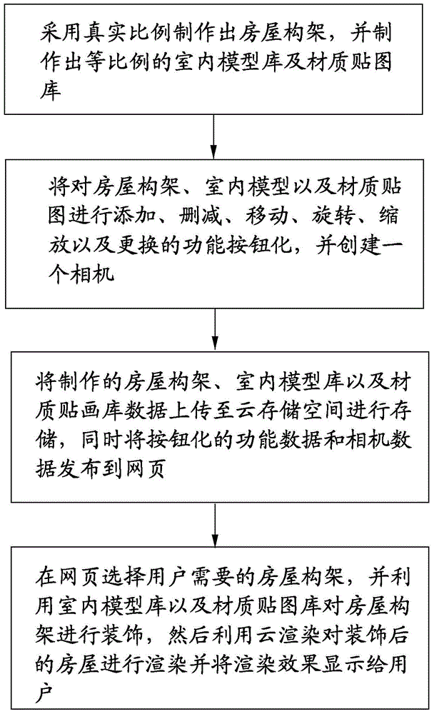
[0017] Please refer to figure 1 As shown, a cloud computing-based indoor custom decoration rendering method, the method includes the following steps:

[0018] Step 10. Make the house structure with the real scale, and make the indoor model library and texture map library with the same proportion.

[0019] During specific implementation, the house structure, indoor model, and texture map are all made by three-dimensional modeling software, that is, the house structure, indoor model, and texture map are all three-dimensional structures, and the house structure, indoor model, and texture map The data are all saved in 3D format, such as OBJ format. Wherein, the indoor model includes doors, windows, tables and chairs, sofas, beds, walls, cabinets, vases or potted plants; the texture maps include tile maps, stone maps, wood maps, leather maps, pattern maps, leaf maps or Metal textures. All the house structures, interior models and texture maps produced are scaled and converted to...


PUM


Abstract

The invention provides an indoor user-defined decoration rendering method based on cloud computing, which comprises the following steps: forming a building frame according to a practical rate and preparing an indoor model library and a texture chart library in equal proportion; arranging function buttons for adding, deleting, moving, rotating, zooming and exchanging the building frame, the indoor model library and the texture chart library, and creating a camera; uploading data of the formed building frame, indoor model library and texture chart library to a cloud storage space and storing the data, and meanwhile, publishing the button functional data and the camera data on a webpage; selecting the building frame required by a user on the webpage, utilizing the indoor model library and the texture chart library to decorate the building frame, and then utilizing the cloud rendering to render the decorated building and showing a rendering effect to the user. According to the indoor user-defined decoration rendering method based on cloud computing, the indoor model library or the texture chart can be freely modified and replaced, the rendering operation is finished by a cloud computing server, and the waste of local resource is reduced.

Description

technical field [0001] The invention relates to the field of house decoration rendering, in particular to a cloud computing-based indoor custom decoration rendering method. Background technique [0002] The current interior decoration of buildings wants to see the effect after decoration. Whether it is a rendering or an animation, it has to go through heavy modeling, calculation and rendering to see the final effect. In this process, it takes many times of communication to understand the customer's ideas. , and in the past, the creation of models, data storage, and model rendering were all implemented on the local computer, so there were the following problems: 1. The rendering of the model required a heavy calculation process, and the computing power of the local computer was limited. Therefore, the rendering of the entire model takes a long time and requires high computer performance. 2. A large amount of data is stored in the local computer, which will also cause a waste...

Claims


Application Information

Patent Timeline
Patent Type & Authority Applications(China)
IPC IPC(8): G06F17/50G06T15/00
Inventor 戴辉评
Owner FUJIAN NARKII INFORMATION TECH
Why Eureka
Try Eureka