
Method and system for detecting sound recording equipment

A technology for recording equipment and playback equipment, applied in speech analysis, instruments, etc., can solve problems such as problems with recorded data, frequency judgment errors, judgment errors, etc.

Active Publication Date: 2015-04-01
FUJIAN STAR NET EVIDEO INFORMATION SYST CO LTD
View PDF7 Cites 16 Cited by
  • Summary
  • Abstract
  • Description
  • Claims
  • Application Information

AI Technical Summary

Problems solved by technology

[0003] 1. No amplitude judgment is made. When the midpoint potential of the A / D converter input signal is abnormal (such as falling or rising), the amplitude range of the A / D converter input signal is abnormal, which may exceed the A / D conversion Due to the range requirements of the input signal of the device, there are problems with the recording data
[0004] 2. No phase judgment is made, and there will be misjudgment problems when the recording equipment phase shifts
[0005] 3. Misjudgment of the frequency. For a sinusoidal signal input with a 1kHz phase of π / 2, there are indeed 2,000 zero-crossing points in 1 second of sampling, but for a 1kHZ square wave, there are also about 2,000 zero-crossing points in 1 second of sampling. Relying on the zero-crossing method cannot accurately judge whether the recording input data is the input data we need. For example, if we input a 1kHz sinusoidal signal with a phase of π / 2 to the recording, the recording process will mutate into other signals. It happens that the mutated signal also has 2000 zero crossings
It does not mean that the recording data is a 1kHz sinusoidal signal; this problem will occur when the recorded data is clipped by the hardware circuit; there is a problem with the recording at this time

Method used


Image

  • Method and system for detecting sound recording equipment
  • Method and system for detecting sound recording equipment
  • Method and system for detecting sound recording equipment

Examples


Embodiment Construction

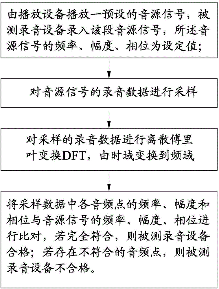
[0047] see figure 1 As shown, a method for recording equipment detection of the present invention includes the following steps:

[0048] Step 1, play a preset sound source signal by the playback device, the recording device under test records the sound source signal, and samples the recording data, the frequency, amplitude, and phase of the sound source signal are set values; for example: the The audio source signal is: the sinusoidal signal source with an input frequency of 1kHz, an amplitude of 2V, and a phase of π / 2 is the left channel recording data source, an input frequency of 2kHz, an amplitude of 2V, and a sinusoidal signal source with a phase of π / 2 It is the right channel recording data source, the audio signal can be an audio file, the amplitude of the audio signal is controlled and played by a fixed player, and the required amplitude can be output by adjusting the output volume of the player to a fixed percentage; such as playing Adjust the volume of the instrumen...


PUM


Abstract

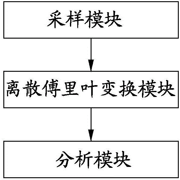
The invention provides a method for detecting sound recording equipment. The method comprises the following steps of 1, playing a preset sound source signal by virtue of playing equipment, recording the section of sound source signal by virtue of the sound recording equipment to be detected, and sampling the sound source signal, wherein the frequency, amplitude and phase of the sound source signal are set values; 2, converting sampled data from the time domain to the frequency domain to obtain the frequency, amplitude and phase of each audio frequency point in the sampled data; 3, comparing the frequency, amplitude and phase of each audio frequency point in the sampled data with the frequency, amplitude and phase of the sound source signal, determining that the sound recording equipment to be detected is qualified if the frequency, amplitude and phase of each audio frequency point in the sampled data are completely consistent with the frequency, amplitude and phase of the sound source signal, and determining that the sound recording equipment to be detected is disqualified if an audio frequency point with inconsistent frequency, amplitude and phase exists. The invention also provides a system for detecting the sound recording equipment. According to the method and the system, the condition of misjudgment of a sound recording interface of the sound recording equipment is avoided, the detection accuracy of the sound recording equipment is higher, a sound recording test is automatically realized, and a test result can be automatically judged and displayed.

Description

technical field [0001] The invention relates to the technical field of voice signal processing, in particular to a method and system for detecting a recording device. Background technique [0002] The traditional recording equipment detection method does not judge the amplitude of the recorded sound, or only relies on the simple zero-crossing method for the detection of the sound source frequency of the recorded sound (that is, for a 1kHz phase π / 2 sinusoidal signal input, sampling 1 second, there are 2000 zero-crossing points), which does not guarantee the accuracy of the recording equipment test. The main disadvantages are as follows: [0003] 1. No amplitude judgment is made. When the midpoint potential of the A / D converter input signal is abnormal (such as falling or rising), the amplitude range of the A / D converter input signal is abnormal, which may exceed the A / D conversion Due to the range requirements of the input signal of the device, there are problems with the ...

Claims


Application Information

Patent Timeline
IPC IPC(8): G10L25/60
Inventor 刘新生喻呈东林鎏娟林剑宇
Owner FUJIAN STAR NET EVIDEO INFORMATION SYST CO LTD
Learn More