High-efficiency discharging feedback type battery charging power source

A battery charging and feedback technology, applied in battery circuit devices, charge balancing circuits, arrangement of multiple synchronous batteries, etc., can solve the problem of high charging harmonic content, increased power loss in power transmission and distribution, grid harmonic loss, and grid distortion. and other problems to achieve the effect of improving power supply power factor, improving power quality and avoiding harmonics

Inactive Publication Date: 2015-04-01
张家港市泓溢电源科技有限公司
View PDF5 Cites 2 Cited by
  • Summary
  • Abstract
  • Description
  • Claims
  • Application Information

AI Technical Summary

Problems solved by technology

The equipment using this technology mainly has the following disadvantages for charging and discharging the battery: (1) The power factor of electricity consumption is low, which will cause harmonic pollution to the power grid. If this equipment is used on a large scale, the power grid will be seriously distorted, which will increase the power loss and loss of power transmission and distribution. Additional grid harmonic losses
The equipment using this technology has the following disadvantages in charging and discharging the battery: (1) The waste of electric energy is large, and all the electric energy discharged by the equipment in this way is consumed by resistance discharge; (2) The high harmonic content of charging will increase additional transmission and distribution Electrical and Harmonic Loss

Method used


Image

  • High-efficiency discharging feedback type battery charging power source
  • High-efficiency discharging feedback type battery charging power source
  • High-efficiency discharging feedback type battery charging power source

Examples


Embodiment Construction

[0016] The present invention is described in further detail now in conjunction with accompanying drawing. These drawings are all simplified schematic diagrams, which only illustrate the basic structure of the present invention in a schematic manner, so they only show the configurations related to the present invention.

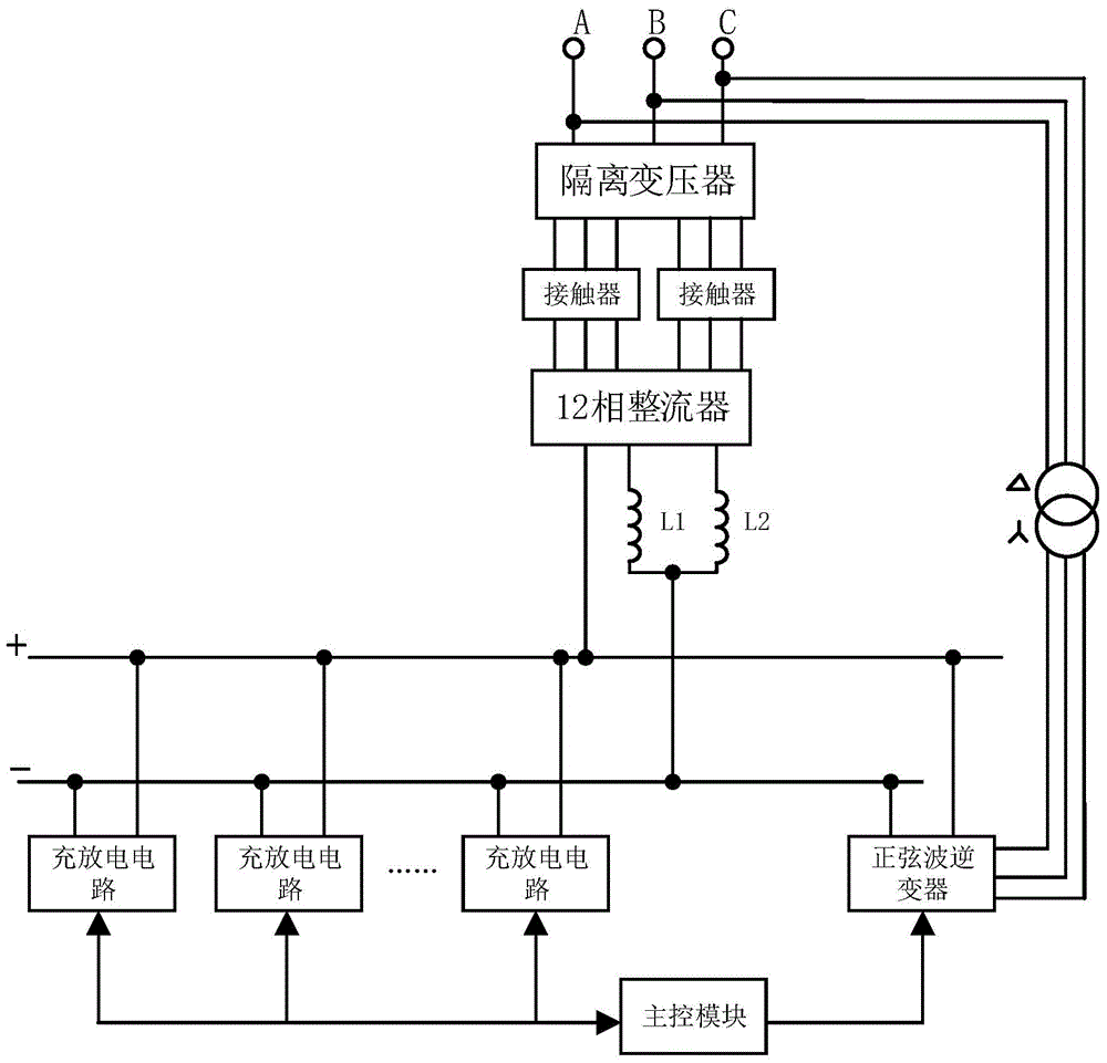
[0017] figure 1 It shows the functional block diagram of the common bus recharging power supply for large dense batteries.

[0018] Such as figure 1 As shown, a high-efficiency discharge feedback battery charging power supply includes a main control module and an isolation transformer connected to the three-phase power supply terminal. The secondary of the isolation transformer is connected in star and delta, and the output terminals of star and delta are The two input ends of the 12-phase rectifier are connected through two interlocking contactors, and the output ends of the 12-phase rectifier are respectively connected through corresponding filter inductor...


PUM


Abstract

The invention relates to a high-efficiency discharging feedback type battery charging power source, which comprises a main control module and an isolation transformer, wherein the isolation transformer is connected with a three-phase power supply end, secondary sides of the isolation transformer are connected by a star and a triangle, the output ends of the star and the triangle are respectively connected with two input ends of a 12-phase rectifier through two interlocking contactors, the output ends of the 12-phase rectifier are respectively connected through corresponding filtering inductances to form a common direct current bus, the common direct current bus is connected with a plurality of charging and discharging circuits and a sine wave inverter in parallel, each charging and discharging circuit comprises a plurality of charging subcircuits and discharging subcircuits for controlling the charging and discharging of the corresponding storage battery, the interior of each charging subcircuit or each discharging subcircuit comprises a power measuring unit, a main control module is connected with the corresponding power measuring unit to collect the charging power of each charging subcircuit and the discharging power of each discharging subcircuit, and the sine wave inverter is controlled to invert the bus voltage back to an alternating current power grid when the total discharging power is greater than the total charging power.

Description

technical field [0001] The invention relates to a high-efficiency discharge feedback type battery charging power supply. Background technique [0002] At present, there are two main charging technologies commonly used in the production process of lead-acid batteries at home and abroad. [0003] The first charging and discharging technology of thyristor circuit adopts thyristor three-phase full-bridge rectification circuit, and the output voltage changes by triggering the thyristor at different times. The equipment using this technology mainly has the following disadvantages for charging and discharging the battery: (1) The power factor of electricity consumption is low, which will cause harmonic pollution to the power grid. If this equipment is used on a large scale, the power grid will be seriously distorted, which will increase the power loss and loss of power transmission and distribution. Additional grid harmonic losses. Therefore, it is necessary to add grid processin...

Claims


Application Information

Patent Timeline
Patent Type & Authority Applications(China)
IPC IPC(8): H02J3/32H02J3/01
CPCH02J7/0019H02J7/04H02J2007/10Y02E40/40
Inventor 朱磊
Owner 张家港市泓溢电源科技有限公司
Why Eureka
Try Eureka