A high-power photovoltaic cabinet body

A high-power, cabinet technology, applied in the field of new energy power generation, can solve the problems of large cabinet size, large number of busbars, and increased cabinet weight, so as to achieve reasonable internal space layout, uniform distribution of busbar heat dissipation, and internal structure compact effect

Active Publication Date: 2017-07-21
TIANJIN RES INST OF ELECTRIC SCI
View PDF5 Cites 0 Cited by
  • Summary
  • Abstract
  • Description
  • Claims
  • Application Information

AI Technical Summary

Problems solved by technology

At present, the general high-power current conversion cabinet structure has the following problems: 1. The size of the cabinet is huge, the installation and use places are very limited, and it is inconvenient to transport; 2. The cabinet is generally composed of an inverter cabinet and a line cabinet , when more powerful equipment is needed, the above two cabinets are superimposed, resulting in a large number of cabinets, bulky equipment, inconvenient transportation, and a large floor area; 3. The layout of the electrical components inside the cabinet is unreasonable, and the internal The layout cannot fully utilize the space of structural parts, resulting in a waste of structural parts materials, which also results in a large cabinet size and increased costs; 4. The busbar wiring inside the cabinet is unreasonable, and the busbar wiring routes are cumbersome, resulting in a large number of busbars. Too much, the cost will increase greatly, and the weight of the cabinet will also increase; and the number of busbars is too large, and there are many lap joints, resulting in excessive heat dissipation, which is not conducive to the heat dissipation inside the cabinet
Therefore, the existing cabinet body has problems such as large equipment cost waste, bulky size, unreasonable structure, inconvenient installation and transportation, etc.
[0003] Through the search of published patent documents, no published patent documents identical to the application of the present invention have been found

Method used


Image

  • A high-power photovoltaic cabinet body
  • A high-power photovoltaic cabinet body
  • A high-power photovoltaic cabinet body

Examples


Embodiment Construction

[0028] The present invention will be further described in detail below with reference to the drawings and specific embodiments. The following embodiments are only descriptive and not restrictive, and the protection scope of the present invention cannot be limited by this.

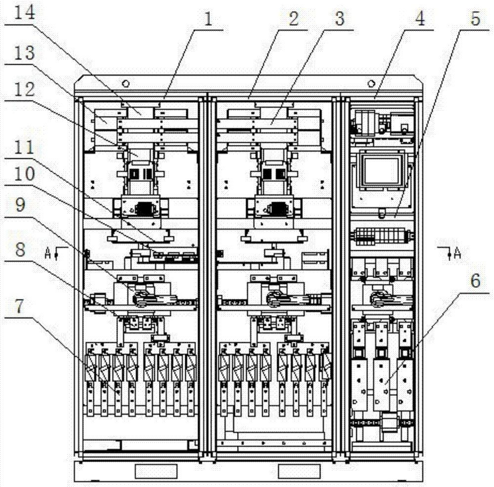
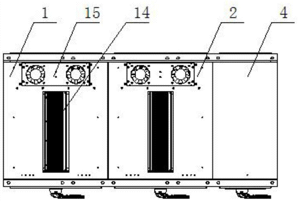
[0029] A high-power photovoltaic combined cabinet body, which is composed of an AC inlet cabinet 4, a left inverter cabinet 1 and a right inverter cabinet 2. The cabinets of three electrical cabinets are fixed side by side to form an overall cabinet frame. The wire cabinet is on the far right.

[0030] The structure of the left and right inverter cabinets is as follows:

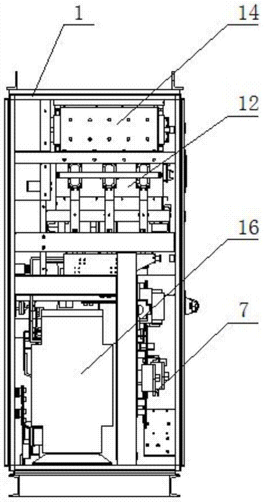
[0031] The power components 13 are fixed in the upper part of the inverter cabinet. The power components are installed on the radiator 12. The front part of the lower part is provided with a circuit breaker 9 and the incoming busbar 7, and the rear part of the lower part is equipped with a reactor assembly 16 and so on. The inverter cabinet has ...


PUM


Abstract

The invention relates to a high-power photovoltaic parallel cabinet, which is composed of an AC incoming cabinet, a left inverter cabinet, and a right inverter cabinet. The cabinets of the three electrical cabinets are fixed side by side to form a whole cabinet frame. The line cabinet is located on the far right; the inside of the cabinet body of the line entry cabinet is divided into two front and rear spaces from top to bottom by the use of neutral columns. The circuit breaker and incoming busbar are installed on the mounting plate, and a magnetic ring is installed on the upper part of the second half. The invention consists of two inverter cabinets and an AC incoming cabinet. After the three cabinets are combined, the current direction is connected through the busbar, the overall structure is compact, and the internal space layout is reasonable. Compared with the traditional inverter cabinet, the The number of cabinets in a complete set of incoming cabinets is reduced by one incoming cabinet, which greatly reduces the cost, and also reduces the weight of the overall equipment, which is convenient for transportation.

Description

Technical field [0001] The invention belongs to the technical field of new energy power generation, and relates to a high-power AC cabinet, in particular a high-power photovoltaic combined cabinet. Background technique [0002] In the field of new energy power generation technology, the existing high-power converter cabinets are often composed of inverter cabinets and input cabinets to form high-power conversion output and input equipment cabinet structures. When more power conversion equipment is required, only the cabinets are combined. Just superimpose, the high-power current converter is generally made into a cabinet structure to facilitate overall transportation and installation. At present, the general high-power current conversion cabinet structure has the following problems: 1. The size of the cabinet is huge, the installation and use place is very limited, and it is not convenient to transport; 2. The cabinet is generally composed of an inverter cabinet and an incoming c...

Claims


Application Information

Patent Timeline
Patent Type & Authority Patents(China)
IPC IPC(8): H02M1/00H05K7/20
CPCY02E10/56
Inventor 刘媛刘佳王国建刘娜李雪飞王诗琪蔡维王玉博刘瑞
Owner TIANJIN RES INST OF ELECTRIC SCI
Why Eureka
Try Eureka