Indoor WLAN (Wireless Local Area Network) equipment supporting structure

A supporting structure and equipment technology, applied in the direction of selection devices, electrical components, etc., can solve the problems of wireless routers connecting power lines and network cables without a fixed place, inconvenient movement and cleaning, and affecting indoor beauty, etc., to achieve fixation and position adjustment , Convenient positioning, keep clean and beautiful effect

Active Publication Date: 2015-04-01
CHENGDU ZHIRONG ZHICHUANG INTPROP MANAGEMENT CO LTD
View PDF4 Cites 2 Cited by
  • Summary
  • Abstract
  • Description
  • Claims
  • Application Information

AI Technical Summary

Problems solved by technology

[0002] At present, there is no special support frame for home wireless routers, and most of them are placed directly on the table or the ground. If it is bad, it will also cause inconvenience to moving and cleaning, and it will also affect the appearance of the interior

Method used


Image

  • Indoor WLAN (Wireless Local Area Network) equipment supporting structure
  • Indoor WLAN (Wireless Local Area Network) equipment supporting structure

Examples


Embodiment 1

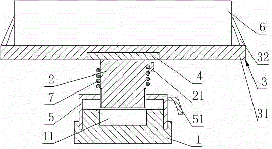
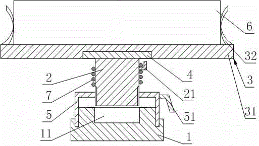
[0015] like figure 1 As shown, the indoor WLAN equipment support structure includes a base 1, a support column 2 and a fixture 3. The fixture 3 includes a connecting block 31 and two opposite elastic clips 32 fixed to the front end of the connecting block 31. The upper end of the supporting column 2 is fixed Connected with a protruding ring 4 whose diameter is larger than that of the support column 2, the lower end surface of the connecting block 31 is provided with a first groove compatible with the protruding ring 4, and the protruding ring 4 is placed in the first groove and has a gap with the first groove Cooperate, the lower end of support column 2 is fixedly connected with the support cylinder 5 that upper and lower ends are all open, and the base 1 is provided with the annular groove that adapts to the opening of support cylinder 5 lower end, and the support cylinder 5 lower end is inserted in the annular groove and is connected with the annular groove. The grooves are ...

Embodiment 2

[0018] In this embodiment, the following further limitations are made on the basis of the embodiment 1: the lower end of the support column 2 is fixedly connected with the support cylinder 5 through threads. In this embodiment, the lower end of the support column 2 may be provided with an external thread, and the opening at the upper end of the support cylinder 5 may be provided with an internal thread matching the external thread. In this way, the relative position of the support column 2 and the support cylinder 5 can be adjusted through screw fit, thereby changing the working height of the support column 2 to meet the suspension requirements of router devices 6 of different sizes, and also meet the requirements of redundant line segments of different lengths. Winding works.

Embodiment 3

[0020] This embodiment is further defined as follows on the basis of embodiment 2: the upper end surface of the base 1 is provided with a second groove 11 capable of accommodating the lower end of the support column 2 . In this embodiment, when the support column 2 is adjusted downward, the lower end of the support column 2 is actually shrunk into the support tube 5. Because the lower end of the support tube 5 is set on the base 1, the lower end of the support column 2 will move downward to place into the second groove 11. In order to ensure the reliability of the present invention, the position of the second groove 11 should be adapted to the lower end of the support column 2, and its depth should be set according to the maximum shrinkage of the support column 2 relative to the support cylinder 5.


PUM


Abstract

The invention discloses an indoor WLAN (Wireless Local Area Network) equipment supporting structure. The indoor WLAN equipment supporting structure comprises a base, a supporting column and a fixture, wherein the fixture comprises a connecting block and two oppositely arranged elastic clamping pieces which are fixedly connected to the front end surface of the connecting block, the upper end of the supporting column is fixedly connected with a convex ring with diameter which is larger than the diameter of the supporting column, a first groove which is adaptive to the convex ring is formed in the lower end surface of the connecting block, the convex ring is arranged in the first groove and is in clearance fit with the first groove, the lower end of the supporting column is fixedly connected with a supporting barrel with openings in upper and lower ends, an annular groove which is adaptive to the opening in the lower end of the supporting barrel is formed in the base, the lower end of the supporting barrel is arranged in the annular groove and is in clearance fit with the annular groove, and a hook piece is arranged on the supporting column. The indoor WLAN equipment supporting structure not only can realize the fixation of a router, but also can realize winding work of a power line and a network line connected with the router, and has the advantages of convenience in positioning, simple operation and low cost.

Description

technical field [0001] The invention relates to the field of communication equipment installation, in particular to an indoor WLAN equipment supporting structure. Background technique [0002] At present, there is no special support frame for home wireless routers, and most of them are placed directly on the table or the ground. If it is bad, it also causes inconvenience to moving and cleaning, and also affects the indoor appearance. Contents of the invention [0003] The purpose of the present invention is to make up for the blank of the support structure of the home router, and provide an indoor WLAN equipment support structure, which can not only realize the fixation of the router, but also realize the winding work of the power line and the network cable connected to the router, and has the advantages of convenient positioning, simple operation, Advantages of low cost. [0004] The purpose of the present invention is mainly achieved through the following technical so...

Claims


Application Information

Patent Timeline
Patent Type & Authority Applications(China)
IPC IPC(8): H04Q1/08
Inventor 谢联峻
Owner CHENGDU ZHIRONG ZHICHUANG INTPROP MANAGEMENT CO LTD
Why Eureka
Try Eureka