
Engine timing chain system assembly tool and an assembly method

A technology of assembly tooling and assembly method, which is applied in the field of engine timing chain system assembly tooling and assembly, and can solve the problems of increased phase deviation between camshaft and sprocket, increased phase deviation between crankshaft sprocket and camshaft sprocket, timing Problems such as chain elongation are not avoided, achieving the effect of reducing phase deviation, improving assembly positioning accuracy, and reducing timing mark design

Active Publication Date: 2015-04-08
CHONGQING CHANGAN AUTOMOBILE CO LTD
View PDF8 Cites 10 Cited by
  • Summary
  • Abstract
  • Description
  • Claims
  • Application Information

AI Technical Summary

Problems solved by technology

Reasons include: if the camshaft and the sprocket are positioned by pins, the phase deviation between the camshaft and the sprocket will increase due to the positional deviation after the pin hole is processed
Another example is that during the assembly process of the timing system, the elongation of the timing chain is not avoided, which also causes the phase deviation between the crankshaft sprocket and the camshaft sprocket to increase

Method used


Image

  • Engine timing chain system assembly tool and an assembly method
  • Engine timing chain system assembly tool and an assembly method
  • Engine timing chain system assembly tool and an assembly method

Examples


Embodiment Construction

[0050] The present invention will be further described in detail below in conjunction with the accompanying drawings and examples. The following examples are only used to explain the present invention, and do not constitute a limitation to the protection scope of the present invention.

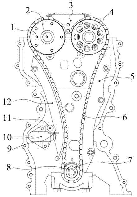
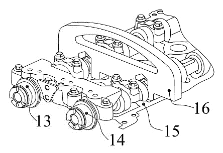
[0051] Such as figure 1 The shown engine timing chain system assembly tooling includes crankshaft timing tooling 17 , camshaft timing tooling 16 and tensioner tooling 11 .

[0052] The front journal of the crankshaft is processed with a keyway, which is assembled and positioned with the crankshaft timing sprocket through a semicircular key. Two pin holes are machined on the rear end surface of the crankshaft for the positioning of the crankshaft timing tool.

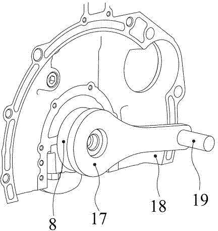
[0053] see image 3 , Figure 4 , the crankshaft timing tool 17 includes a flange body 171, a connecting arm 172 and a latch 19, two positioning pins 173 are arranged on the inner end surface of the flange body, and the two positionin...


PUM


Abstract

The invention discloses an engine timing chain system assembly tool and an assembly method. The assembly tool comprises a crank timing tool, a cam shaft timing tool and a tensioner tool. Through the adoption of the assembly tool provided by the invention, the assembly positioning accuracy can be effectively improved.

Description

technical field [0001] The invention relates to the technical field of engine manufacturing, in particular to an assembly tool and an assembly method for an engine timing chain system. Background technique [0002] Engine valve timing is based on the top dead center or bottom dead center of the piston, and the timing of opening and closing of the intake and exhaust valves is measured by the crankshaft angle. In the manufacturing process, due to the existence of component manufacturing deviations, engine assembly deviations, and sensor signal induction deviations, the originally specified valve timing will be changed to varying degrees, such as delayed or advanced valve opening and closing times, and disordered intake and exhaust phases. Wait. The phase deviation will lead to the decline of engine power, poor economy and emission deterioration. When the phase deviation is large, the engine cannot be started at all. In severe cases, the piston will hit the valve, the valve st...

Claims


Application Information

Patent Timeline
IPC IPC(8): B25B27/22
CPCB25B27/22
Inventor 张云富李春肖航黄参何海珠
Owner CHONGQING CHANGAN AUTOMOBILE CO LTD
Learn More