Check patentability & draft patents in minutes with Patsnap Eureka AI!

Conveyor and control method

A technology of conveying device and control method, applied in the fields of transportation and operation, can solve problems such as affecting production efficiency, inability to precisely control, and uncertain motion trajectory, and achieve the effects of easy operation and maintenance, improved qualification rate, and simple structure

Inactive Publication Date: 2015-04-08
GUANGZHOU TECH LONG PACKAGING MACHINERY CO LTD
View PDF10 Cites 7 Cited by
  • Summary
  • Abstract
  • Description
  • Claims
  • Application Information

AI Technical Summary

Problems solved by technology

[0003] However, this bottle storage platform only has the guide plate on the edge as a guide. When the forward direction is blocked, the bottles will be blocked and accumulated at the output port, and the input chain will continuously send bottles, and the subsequent bottles will collide with the accumulated bottles. pressure, causing the bottles to spread along both sides of the stacking place until the entire platform is full of bottles, and the input chain will stop. The greater the pressure of the bottle, the bottle whose front end is in contact with the guide plate has the highest pressure
With the enlargement and growth of the platform and the accumulation of more and more bottles, this pressure will also increase, and these pressures will always cause the surface of the bottle to be scratched or scratched, or the shape of the bottle will be deformed, which will seriously damage the bottle. Become waste products, seriously affecting production efficiency and increasing production costs
[0004] In addition, the bottles move passively on the platform and squeeze and collide with each other, their trajectory is uncertain, and due to the limitation of mutual extrusion, the entire bottle storage section is often unable to be completely filled and then forced to stop
Therefore, this method cannot truly determine the capacity of the bottle storage platform that can actually store bottles, cannot accurately determine the full load moment of the bottle storage section, and cannot precisely control when to stop feeding bottles into the bottle storage platform, resulting in more serious conflicts between the bottles. extrusion

Method used


Image

  • Conveyor and control method
  • Conveyor and control method
  • Conveyor and control method

Examples


Embodiment Construction

[0037] Embodiments of the present invention are described in detail below:

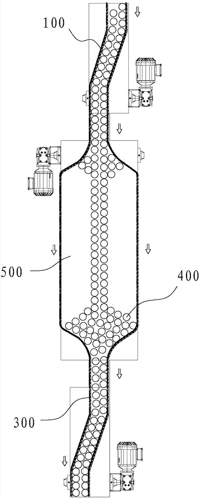
[0038] figure 1 It is a structural schematic diagram of the existing bottle storage platform, and the bottles that cannot be sent away in time can be accumulated on the bottle storage platform 500 .

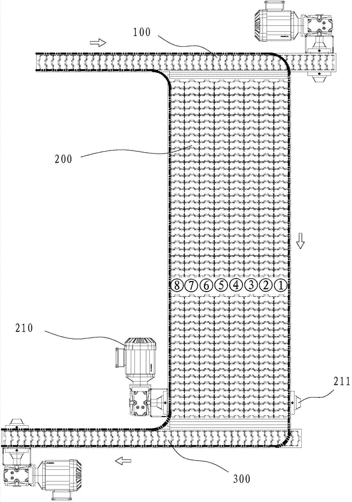
[0039] like Figures 2 to 3 As shown, the conveying device has an input channel 100, an output channel 300, and a plurality of buffer conveyors 200, and the buffer conveyors 200 are arranged in parallel, and the buffer conveyor 200 has an input port and an output port, and each input port is arranged in parallel. The same side is vertically connected, and the output ports are arranged in parallel and connected to the same side of the output channel 300 , and the input channel 100 and the output channel 300 are arranged at both ends of the buffer conveyor 200 .

[0040] It also includes a first guide plate 601 and a second guide plate 602. The first guide plate 601 transitions from the conveying direction...


PUM


Abstract

The invention relates to a conveyor and a control method. The conveyor comprises an input passage, an output passage, at least two buffer conveying passages and a switcher, each buffer conveying passage is provided with an inlet and an outlet, all the inlets are arranged in parallel, and all the outlets are arranged in parallel, and the switcher is used for switching the input passage to be docked with any one of the inlets and switching the output passage to be docked with any one of the outlets. Mutual squeezing among products and squeezing between the products and the conveyor are avoided effectively, deformation and damage to the products due to squeezing force are avoided, product qualified rate is increased, buffer capacity is determined, and start and stop of an entire conveying system can be controlled accurately.

Description

technical field [0001] The invention belongs to the field of operation and transportation, and in particular relates to a conveying device and a control method. Background technique [0002] During the production, the bottles processed by the previous equipment need to be sent to the next equipment for processing. Because the production process of each process is not synchronized, and the bottles sent by the front end cannot be sent away in time due to the back-end equipment failure, shutdown and other reasons. , resulting in production stagnation and losses. In this regard, the existing bottle chain generally adopts the method of setting a bottle storage platform, such as figure 1 As shown, the bottles that cannot be sent away in time can be accumulated on the bottle storage platform 500, so as to alleviate the blockage of some bottles. [0003] However, the bottle storage platform only has the guide plate on the edge as a guide. When the forward direction is blocked, the...

Claims


Application Information

Patent Timeline
Patent Type & Authority Applications(China)
IPC IPC(8): B65G47/30
Inventor 潘冬霞黄巨柏周芳何令
Owner GUANGZHOU TECH LONG PACKAGING MACHINERY CO LTD
Features
  • R&D
  • Intellectual Property
  • Life Sciences
  • Materials
  • Tech Scout
  • Unparalleled Data Quality
  • Higher Quality Content
  • 60% Fewer Hallucinations
Learn More