Wind load control system, method and apparatus and hoisting equipment

A lifting equipment and control system technology, applied in cranes, transportation and packaging, load hanging components, etc., can solve the problems of inaccurate control results and too general control methods.

Active Publication Date: 2015-04-08
ZOOMLION HEAVY IND CO LTD
View PDF7 Cites 7 Cited by
  • Summary
  • Abstract
  • Description
  • Claims
  • Application Information

AI Technical Summary

Problems solved by technology

[0007] The embodiment of the present invention provides a wind load control system, method, device and lifting equipment to solve the problem that the control method of the existing wind load control scheme is too general and the control result is inaccurate

Method used


Image

  • Wind load control system, method and apparatus and hoisting equipment
  • Wind load control system, method and apparatus and hoisting equipment
  • Wind load control system, method and apparatus and hoisting equipment

Examples


Embodiment 1

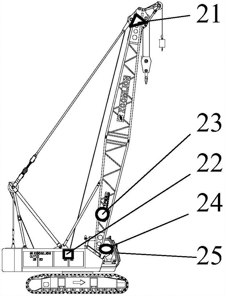
[0030] Embodiment 1 of the present invention provides a wind load control system, such as figure 2 As shown, it is a schematic structural diagram of the wind load control system in Embodiment 1 of the present invention, and the wind load control system may include:

[0031] The wind speed measuring device 21 can be used to measure the current wind speed of the jib head of the lifting equipment, that is, measure the current wind speed of the jib head of the lifting equipment;

[0032] The hook position measuring device 22 can be used to measure the current hook position of the lifting device, that is, measure the current position of the hook of the lifting device, wherein the current position of the hook of the lifting device usually refers to the hook position of the lifting device. The height of the hook from the horizontal plane where the lifting device is located;

[0033] The jib elevation angle measuring device 23 can be used to measure the current jib elevation angle o...

Embodiment 2

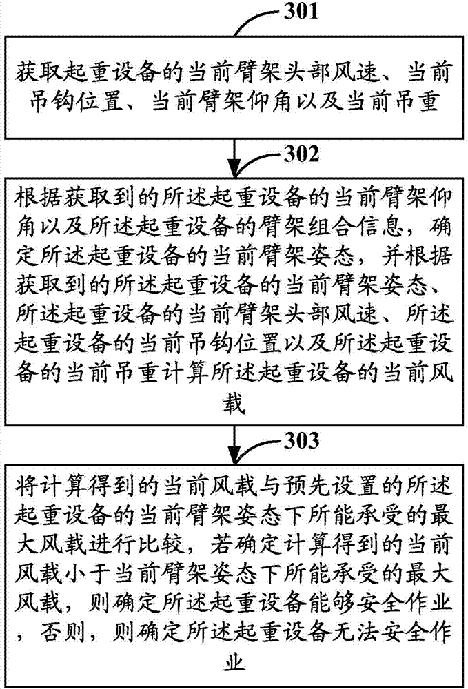
[0062] Based on the same inventive concept, Embodiment 2 of the present invention provides a wind load control method, such as image 3 As shown, it is a schematic flow chart of the wind load control method described in Embodiment 2 of the present invention, and the wind load control method may include the following steps:

[0063] Step 301: Obtain the current wind speed at the head of the jib, the current position of the hook, the current elevation angle of the jib, and the current hoisting weight of the lifting device.

[0064] Specifically, the execution subject of each step in Embodiment 2 of the present invention may generally be the wind load control device described in Embodiment 1 of the present invention, which will not be described in detail in this embodiment of the present invention.

[0065] Optionally, obtaining the current wind speed at the head of the jib, the current position of the hook, the current elevation angle of the jib, and the current lifting weight o...

Embodiment 3

[0099] Based on the same inventive concept, Embodiment 3 of the present invention provides a wind load control device, such as Figure 4 As shown, it is a schematic structural diagram of the wind load control device in Embodiment 3 of the present invention, and the wind load control device may include:

[0100] The obtaining module 41 can be used to obtain the current wind speed at the head of the jib, the current position of the hook, the current elevation angle of the jib and the current hoisted weight of the lifting equipment. Optionally, the acquiring module 41 can be specifically configured to acquire the current wind speed at the jib head of the lifting equipment from the anemometer located at the jib head of the lifting equipment, The current hook position of the lifting device is obtained from the angle encoder, the current jib elevation angle of the lifting device is obtained from the angle sensor located at the bottom of the jib of the lifting device, and the startin...


PUM


Abstract

The invention discloses a wind load control system, method and apparatus and hoisting equipment. According to the current boom elevation angle and the boom combined information of the hoisting equipment, the current boom gesture of the hoisting equipment is determined; the current wind load of the hoisting equipment is calculated based on a current boom head wind speed, a current lifting hook position and a current lifting weight; the current wind load is compared with the maximum wind load born under the current boom gesture so as to determine whether the hoisting equipment can work safely; therefore, quantitative analysis on the wind load of the hoisting equipment can be achieved according to different boom gestures, the accuracy and the safety of hoisting control under the effect of wind load are improved, and the purposes of widening the working range of the hoisting equipment and improving the attendance rate, namely utilization rate, of the hoisting equipment are achieved. Moreover, due to comprehensive consideration of the influence of such factors as current lifting weight on the wind load, the wind load control system disclosed by the invention can be used for further improving the accuracy of hoisting control compared with the prior art which just takes the influence of wind speed on the wind load into consideration.

Description

technical field [0001] The invention relates to the technical field of lifting equipment safety control, in particular to a wind load control system, method, device and lifting equipment. Background technique [0002] Crawler cranes, as a kind of special operating machinery, are widely used in nuclear power, wind power and other fields due to their many jib combinations, large lifting capacity, and strong mobility. In the above fields, the hoisting operation is basically outdoors, and the uncertainty of the environment has a great impact on the safety of the hoisting operation and the progress of the construction work. On this basis, wind load is a very important environmental factor in crane safety. The field of control has received extensive attention. [0003] Specifically, at present, in order to monitor the impact of wind load on the crane operation, to ensure the safety of the crane operation and to expand the operating range of the crane, the industry mainly adopts t...

Claims


Application Information

Patent Timeline
Patent Type & Authority Applications(China)
IPC IPC(8): B66C13/16B66C23/62
CPCB66C13/16B66C23/62B66C2700/08
Inventor 刘小华尹莉王冲钟懿任会礼
Owner ZOOMLION HEAVY IND CO LTD
Why Eureka
Try Eureka