
Tower crane type concrete delivery device

A conveying device and concrete technology, which is applied in the direction of transportation, packaging, cranes, etc., can solve the problems of installation and disassembly being limited by the installation location, concrete construction cannot be carried out, and the distribution range of the distribution machine is small, so as to improve uniformity and convenience. The effect of height increase, service life and work efficiency improvement

Inactive Publication Date: 2015-04-08
吴春生
View PDF5 Cites 5 Cited by
  • Summary
  • Abstract
  • Description
  • Claims
  • Application Information

AI Technical Summary

Problems solved by technology

[0002] At present, in the construction of the construction industry, there are various concrete pouring methods and equipment, and the commonly used ones include concrete pouring in boxes lifted by the tower crane hook, but the continuity is poor, and the output cannot be controlled during pouring, vibration The uniformity is poor, the speed is slow, the labor cost is high, the cloth distribution machine is small and inflexible, and each installation and disassembly is limited by the installation location; or the ground pump and pump truck are used for pouring, but the pouring is limited by the height of the boom The height is limited, and it is impossible to carry out large-scale concrete construction in high-rise buildings.

Method used


Image

  • Tower crane type concrete delivery device
  • Tower crane type concrete delivery device
  • Tower crane type concrete delivery device

Examples


Embodiment Construction

[0024] The present invention will be further described in detail below in conjunction with the accompanying drawings, which are explanations rather than limitations of the present invention.

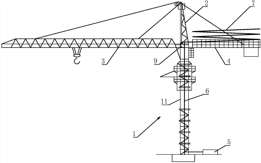
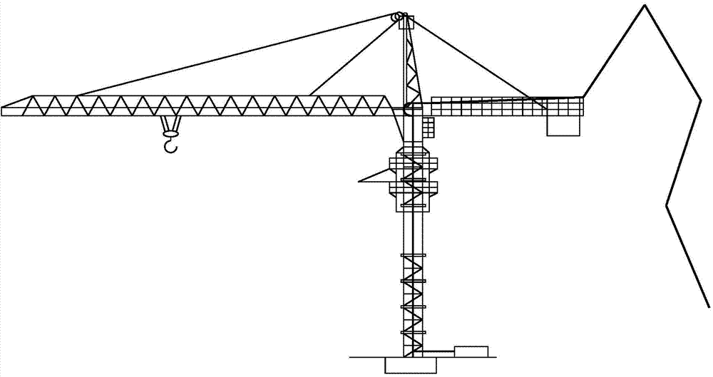
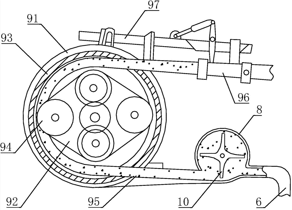
[0025] A kind of tower crane type concrete conveying device of the present invention, as figure 1 As shown, it includes a tower 1, a tower cap 2 arranged on the upper end of the tower 1, a lifting arm 3 and a balance arm 4 horizontally connected to the upper end of the tower 1 through a turntable, and a feeding pump 5, a feeding pipe 6 and an arm Frame 7; the boom 7 is folded and arranged on the balance arm 4, the input end of the boom 7 is connected to the output end of the feeding pump 5 through the feeding pipe 6 fixed on the tower 1, and the feeding pump 5 is arranged on the tower 1 outside of the base; as image 3 As shown, the delivery pipe 6 is provided with an acceleration pump 8 for accelerating the flow of concrete material, and a supercharging device 9 is arranged downstream ...


PUM


Abstract

The invention relates to a tower crane type concrete delivery device which comprises a tower truss, a tower cap, a lifting arm, a balance arm, a delivery pump, a delivery pipe and an arm frame, wherein the tower cap is arranged on the upper end of the tower truss; the lifting arm and the balance arm are horizontally connected with the upper end of the tower truss through rotating discs; the arm frame is arranged on the balance arm in a folded way, the input end of the arm frame is connected with the output end of the delivery pump through the delivery pipe fixed on the tower truss, and the delivery pump is arranged outside a base of the tower truss; the delivery pipe is provided with an accelerating pump used for accelerating the flow of a concrete material. According to the tower crane type concrete delivery device, the arranged tower truss serves as a support and guide structure of the delivery pipe, so that the height of a delivered material can be increased, and the synchronous adjustment of the height is carried out along the lifting of the tower truss; in addition, the arm frame is arranged on the balance arm, under a general condition, extra weight counterbalance is unnecessary, additionally, the height is changed with the height of the tower truss, and the output end of the arm frame is positioned above a pouring part all the time, so that the stability of the pitch number of the arm frame can be kept, the height is increased, the cost is less increased, and high working efficiency and low cost are achieved.

Description

technical field [0001] The invention belongs to the field of concrete conveying, in particular to a tower crane type concrete conveying device. Background technique [0002] At present, in the construction of the construction industry, there are various concrete pouring methods and equipment. The commonly used ones include concrete pouring in boxes lifted by tower crane hooks, but the continuity is poor, and the output cannot be controlled during pouring, vibration The uniformity is poor, the speed is slow, the labor cost is high, the cloth distribution machine is small and inflexible, and each installation and disassembly is limited by the installation location; or the ground pump and pump truck are used for pouring, but the pouring is limited by the height of the boom The height of the concrete is limited, and it is impossible to carry out large-scale concrete construction in high-rise buildings. Contents of the invention [0003] Aiming at the problems existing in the ...

Claims


Application Information

Patent Timeline
IPC IPC(8): B66C23/72B66C23/62
CPCB66C23/62B66C23/72B66C2700/03
Inventor 吴春生
Owner 吴春生
Learn More