Active Beam of a Segmental Turnout

An active beam and segment technology, applied in the field of rail transit system, can solve problems such as easy failure, increase failure sources, and difficult installation, save manufacturing costs and construction costs, reduce the type and number of parts, and simplify turnouts. The effect of beam structure

Active Publication Date: 2016-04-13
CHINA RAILWAY CONSTR HEAVY IND
View PDF5 Cites 0 Cited by
  • Summary
  • Abstract
  • Description
  • Claims
  • Application Information

AI Technical Summary

Problems solved by technology

[0006] Just because the existing active beams need to pass through the figure 1 The vertical positioning device shown is for positioning adjustment. The vertical positioning device is a separate device with a complex structure and difficult installation, which increases the structural cost and construction cost.
The addition of devices and components also increases potential sources of failure
And compared to the turnout beam, the movable end where the vertical positioning device is located is a weak link, and the vibration is very large when the train passes, which is prone to failure

Method used


Image

  • Active Beam of a Segmental Turnout
  • Active Beam of a Segmental Turnout
  • Active Beam of a Segmental Turnout

Examples


Embodiment Construction

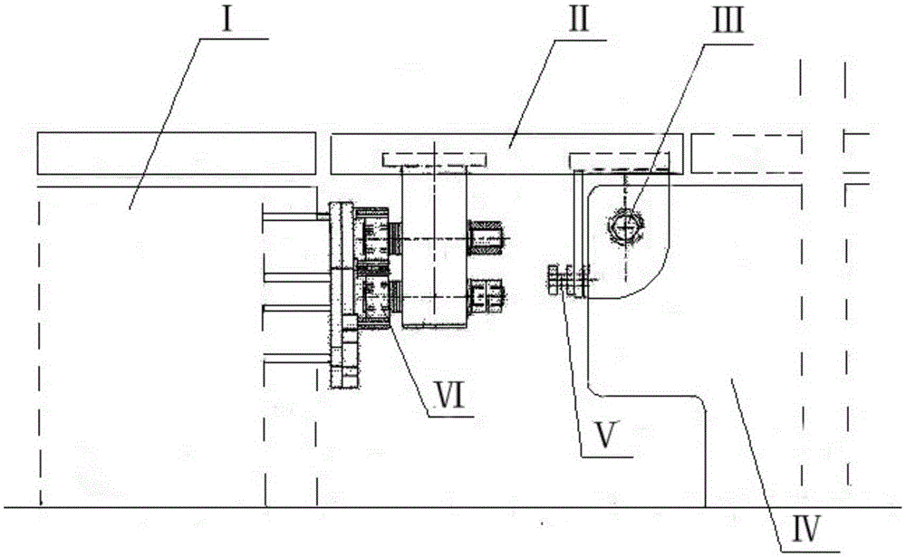
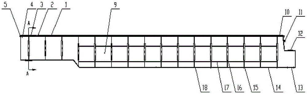
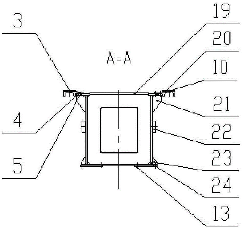
[0022] Figure 2-5 The active beam of a segmental turnout provided by the present invention is shown in the figure, comprising a main beam body 9, a main beam upper flange plate 10, a main beam F rail 1 above the main beam upper flange plate 10, an adjustment rail 3, and an F rail Mounting plate 2, mounting plate 5 and adjustment assembly 4, described adjusting rail 3 is used for main girder F rail 1 and is positioned at movable end stacking beam F rail 6 above the upper flange plate 8 of movable end stacking beam joint (connecting flat), described One end of the adjustment rail 3 and one end of the main beam F rail 1 are all fixedly arranged on the upper flange plate 10 of the main beam through the same F rail mounting plate 2, and the two are arranged to be flush in the height direction, and the adjustment rail The other end of 3 and / or its middle are fixedly connected to the upper flange plate 10 of the main girder through the adjustment assembly 4 and the installation plat...


PUM


Abstract

The invention provides a driving beam of a segmental turnout. The driving beam comprises a main beam body 9, a main beam upper flange plate 10, a main beam F-rail 1 located above the main beam upper flange plate 10, an adjusting rail 3, an F-rail mounting plate 2, a mounting plate 5 and an adjusting component 4. The adjusting rail 3 is used for flatly connecting the main beam F-rail 1 and a moving end butt beam F-rail 6 located above a moving end butt beam upper flange plate 8. The driving beam allows a turnout beam to be switched in place, with left-right and vertical degrees of freedom both limited, the moving end F-rail and a fixed end F-rail are flatly connected, and no leap occurs when a train passes by. Compared with the prior positioning techniques, the driving beam has the advantages that complex positioning connectors for use at the moving end of the F-rail of the turnout are omitted, a weak and fragile link is omitted, safety is improved at the premise of ensuring service performance; the whole turnout beam structure is simplified, fewer parts of fewer varieties are used, mounting is simplified, and manufacturing cost and construction cost are saved.

Description

technical field [0001] The invention relates to a rail transit system, in particular to an active beam used in a segmental turnout of a maglev transportation system. Background technique [0002] The medium and low speed maglev rail transit system has many advantages such as low energy consumption, low vibration, good ride quality, strong line adaptability (large climbing ability, small line curve radius), low construction and operation costs, etc. It is a very competitive means of transportation in rail transit and intercity rail transit, and has broad development prospects. [0003] In order to make the low- and medium-speed maglev turnout have the steering function, the turnout beam of the maglev turnout must be able to switch from one position to another. Due to manufacturing errors, post-construction settlement and other reasons between the movable end stacking beam and the active beam, the F rail cannot be aligned and cannot meet the requirements of train passing. At ...

Claims


Application Information

Patent Timeline
Patent Type & Authority Patents(China)
IPC IPC(8): E01B25/34
CPCE01B25/34E01B2202/027
Inventor 程永亮刘海华周文张亚军谭萍罗震
Owner CHINA RAILWAY CONSTR HEAVY IND
Why Eureka
Try Eureka