The output end of the wind turbine yaw and pitch gearbox

A technology for wind turbines and output terminals, applied in the field of output terminals, which can solve problems such as inability to replace on-site, difficulties in lifting and disassembly, and achieve the effects of weight reduction, convenient disassembly and assembly, and reduced probability of mutual influence

Active Publication Date: 2017-03-29
NANJING HIGH SPEED & ACCURATE GEAR GRP
View PDF5 Cites 0 Cited by
  • Summary
  • Abstract
  • Description
  • Claims
  • Application Information

AI Technical Summary

Problems solved by technology

[0006] The purpose of the present invention is to solve the mutual influence between the reduction mechanism and the output mechanism of the current wind power generation yaw reducer and the variable pitch gear box after the failure occurs, and it is difficult to lift and disassemble on site during maintenance, and the two roller bearings on the output shaft The actual problem that the oil seal used to seal and lubricate cannot be replaced on site, improve the output end of the yaw reducer and the pitch gearbox, and provide a new output end of the wind turbine yaw and pitch gearbox

Method used


Image

  • The output end of the wind turbine yaw and pitch gearbox
  • The output end of the wind turbine yaw and pitch gearbox
  • The output end of the wind turbine yaw and pitch gearbox

Examples


Embodiment Construction

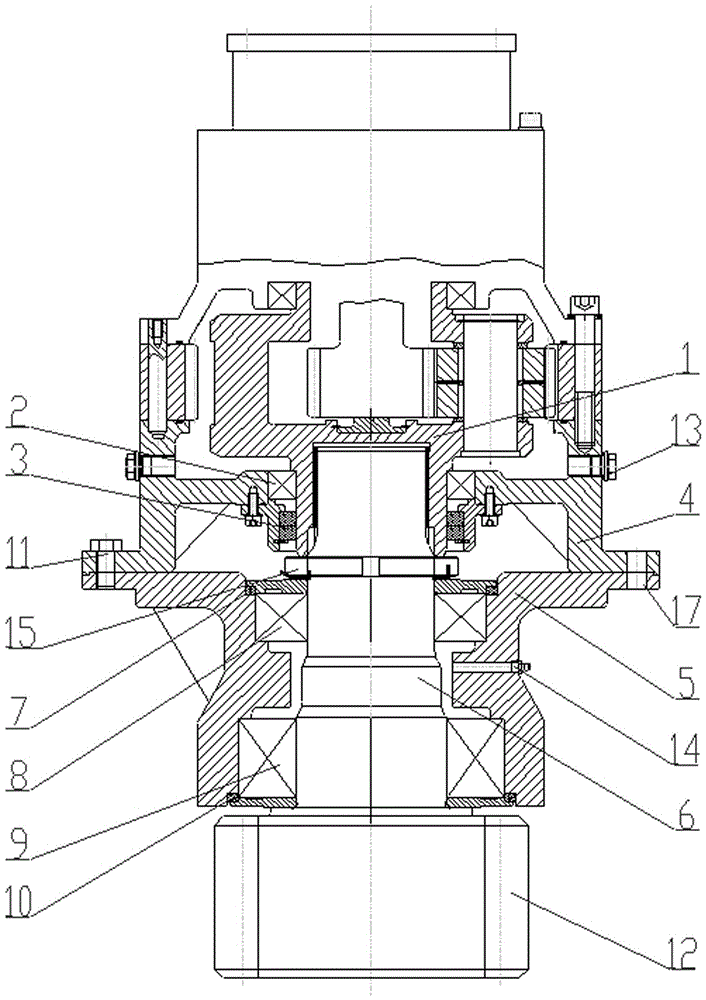
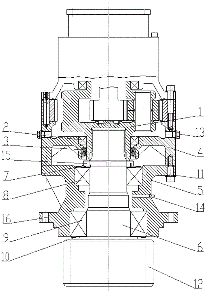
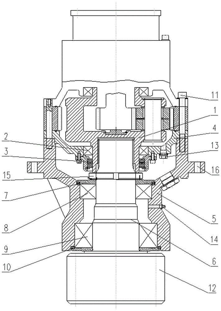
[0020] figure 1 , figure 2 with image 3 The specific structures of different embodiments of the present invention are disclosed respectively, and the embodiments of the present invention will be further described below in conjunction with the accompanying drawings.

[0021] Depend on figure 1 , figure 2 with image 3 It can be seen that they are all equipped with an output end box, an output end 1 of the final planetary carrier that passes through the sealing ring, a transmission shaft that is docked with the output end 1 of the final stage planetary carrier, and an output shaft supporting bearing and a sealing ring, wherein: the output The end box includes the rear box 4 of the final planetary gear train and the support box 5 of the transmission shaft. The rear box 4 and the support box 5 are connected by bolts 11. The output end 1 of the planetary carrier and the transmission shaft 6 are located at the The sealed space between the rear box body 4 and the support box ...


PUM


Abstract

The invention relates to an output end of a wind driven generator yawing and pitch-varying gear box. An output end box body comprises a rear box body of a final-stage planetary wheel system and a supporting box body of a transmission shaft, wherein the rear box body is connected with the supporting box body through bolts; a butting region of the output end of a final-stage planetary frame and the transmission shaft is positioned in a sealed space between the rear box body and the supporting box body; an oil discharging plug screw is arranged on the rear box body; an oil injection opening is formed in the supporting box body; the output end of the final-stage planetary frame is supported on the rear box body through a bearing; the bearing is arranged in lubricating oil; a framework type sealing ring is arranged on the outer side of the bearing; two roller bearings are arranged on the supporting box body; the oil injection opening is positioned between the two roller bearings; the two roller bearings are arranged in the lubricating oil; sealing rings are arranged on the outer sides of the two roller bearings; one end of the transmission shaft penetrates through the two roller bearings and is arranged in the sealed space between the rear box body and the supporting box body; an external spline at the end part and a matched internal spline are butted; the other end of the transmission shaft is arranged outside the supporting box body; a driving gear is arranged at the end part of the transmission shaft.

Description

technical field [0001] The patent of the present invention relates to an output end of a wind power generator yaw and pitch gearbox. Background technique [0002] The yaw and pitch gearbox is one of the important components of the wind turbine. Since wind farms are mostly located in remote areas with inconvenient transportation and harsh natural environments; and the yaw variable pitch gearbox is installed in the cabin tens of meters away, the space is small and maintenance is difficult; as wind turbines become larger and offshore models With the development, the weight and volume of yaw and pitch are getting bigger and bigger, and the maintenance is more inconvenient. Once the yaw variable pitch gearbox fails, it may cause the wind turbine to stop for a long time, which will cause huge economic losses to the owner. Therefore, these put forward very high requirements for the convenience of maintenance of the yaw pitch gearbox. [0003] The existing yaw-pitch gearbox gener...

Claims


Application Information

Patent Timeline
Patent Type & Authority Patents(China)
IPC IPC(8): F16H57/02F16H57/021F16H57/023
CPCF16H57/02F16H57/021F16H57/023F16H2700/00
Inventor 李苏东陈武夏权栋杜树军朱琰
Owner NANJING HIGH SPEED & ACCURATE GEAR GRP
Why Eureka
Try Eureka