Assembly and rectification method for collimator

A collimating light tube, calibrating technology, applied in measuring devices, testing optical performance, instruments, etc., can solve the problems of large randomness, long calibrating cycle, low calibrating accuracy, etc., to reduce non-parallelism, improve Accuracy of installation and calibration, overcoming the effect of strong randomness

Inactive Publication Date: 2015-04-08
BEIJING ZHENXING METROLOGY & TEST INST
View PDF3 Cites 13 Cited by
  • Summary
  • Abstract
  • Description
  • Claims
  • Application Information

AI Technical Summary

Problems solved by technology

The traditional collimator installation and calibration process currently used can only be carried out by relying on the operator's installation and calibration experience, which has the disadvantages of long installation and calibration cycle, large randomness, and low installation and calibration accuracy.

Method used


Image

  • Assembly and rectification method for collimator
  • Assembly and rectification method for collimator
  • Assembly and rectification method for collimator

Examples


Embodiment 1

[0062] Such as Figure 5 As shown, it is a layout diagram for realizing the measurement of the optical path in a preferred embodiment of the collimator installation method of the present invention, wherein, in order to realize the measurement of the wave aberration of the collimator, this embodiment adopts the interference The interferometer is placed at the focal plane of the collimator light pipe. The interferometer emits a standard spherical wave. The spherical wave is collimated by the light pipe to form a parallel beam and hits the plane mirror at the exit. The incoming light is reflected by the plane mirror. In the optical path of the tube, it is reflected by the primary mirror at the front end of the interferometer to perform interference imaging with the standard spherical wave, and the interferometer obtains the wave surface information, and then obtains the Zernike coefficient.

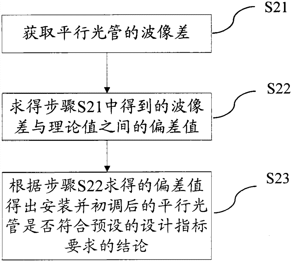
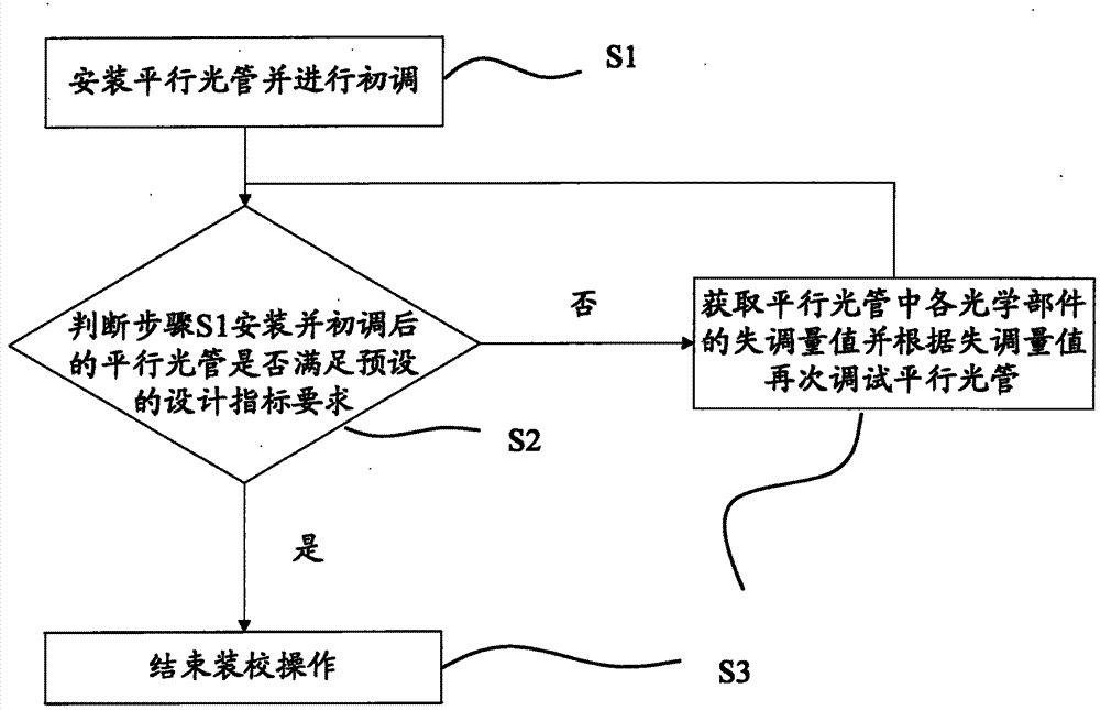
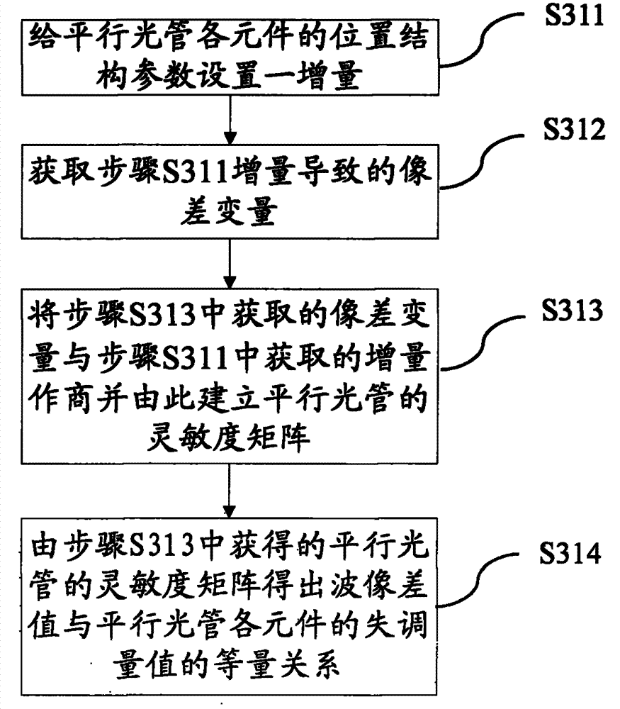
[0063] Such as Figure 6 As shown, it is the flow chart of collimator installation and ...


PUM


Abstract

The invention provides an assembly and rectification method for a collimator. The method comprises the following steps: S1, installing the collimator and performing primary adjustment on the collimator; S2, judging whether the collimator installed and subjected to primary adjustment in the step S1 meets preset design index requirements; and S3, if the collimator does not meet the preset design index requirements according to the judging result of the step S2, obtaining an imbalance quantity value of each optical component of the collimator and re-adjusting the collimator according to the imbalance quantity value, and if the collimator meets the preset design index requirements, finishing the assembly and rectification operation. The assembly and rectification method can be used for realizing the fast and accurate assembly and rectification of the collimator, the defects that the traditional assembly and rectification method is strong in randomness, long in assembly and rectification period and the like are overcome, the precision of the assembly and rectification of the collimator is markedly improved, and the nonparallelism of the collimated light beam is decreased.

Description

technical field [0001] The invention relates to the field of assembling and calibrating optical testing equipment, in particular to a method for assembling and calibrating a collimator. Background technique [0002] With the rapid development of aerospace technology, high-precision star sensors are gradually used as navigation devices in weapon systems and aerospace vehicles, and the guidance accuracy of infrared seekers used is getting higher and higher. Calibration is an indispensable process in the development of star sensors and infrared seekers. This process is usually carried out in ground laboratories. As the most commonly used calibration equipment, the role of collimators is particularly important. . However, the existing collimator can only meet the ground calibration of medium-precision star sensors. If we want to meet the calibration requirements of higher-precision star sensors, the accuracy of the collimator needs to be greatly improved. The precision of the ...

Claims


Application Information

Patent Timeline
Patent Type & Authority Applications(China)
IPC IPC(8): G01C25/00G01M11/02
CPCG01C25/00
Inventor 孙广尉任小婉
Owner BEIJING ZHENXING METROLOGY & TEST INST
Why Eureka
Try Eureka