Probe servo angle control method and control mode, imaging system based on control module and imaging method of system

An angle control, probe technology, applied in scanning probe technology, scanning probe microscopy, measuring devices, etc., can solve problems such as inability to continuously control

Active Publication Date: 2015-04-08
HARBIN INST OF TECH
View PDF8 Cites 11 Cited by
  • Summary
  • Abstract
  • Description
  • Claims
  • Application Information

AI Technical Summary

Problems solved by technology

[0003] The purpose of the present invention is to solve the problem that the traditional atomic force microscope cannot realize continuous and controllable resolution three-dimensional scanning imaging on structural surfaces with large inclination angles, such as outer inclined surfaces, vertical side wall surfaces, and inner inclined surfaces, and provide a probe servo angle Control method and control module, imaging system based on the control module and imaging method of the system

Method used


Image

  • Probe servo angle control method and control mode, imaging system based on control module and imaging method of system
  • Probe servo angle control method and control mode, imaging system based on control module and imaging method of system
  • Probe servo angle control method and control mode, imaging system based on control module and imaging method of system

Examples


specific Embodiment approach 1

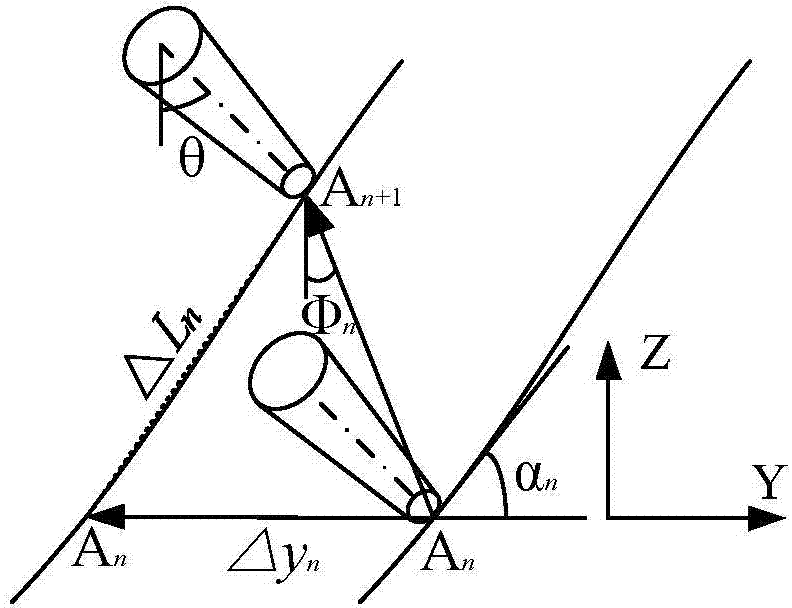
[0038] Specific implementation mode one: combine figure 1 with Figure 9 To illustrate this embodiment, the probe servo angle control method described in this embodiment includes the following steps:

[0039] Coordinate value collection step: collect the current coordinate value of the nanopositioning stage that drives the probe or the sample stage to move during the scanning process; and execute the probe servo angle calculation step after this step;

[0040] Probe servo angle calculation steps: Φ n = 1 2 Σ i = 1 m ( Σ j = 1 p arctan ( z ( ...

specific Embodiment approach 2

[0056] Embodiment 2: The probe servo angle control module described in this embodiment includes the following devices:

[0057] Coordinate value acquisition device: collect the current coordinate value of the nanopositioning stage that drives the probe or sample stage to move during the scanning process; and start the probe servo angle calculation device after the device runs;

[0058] Probe servo angle calculation device: Φ n = 1 2 Σ i = 1 m ( Σ j = 1 p arctan ( z ( n - ...

specific Embodiment approach 3

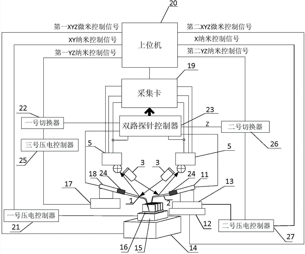
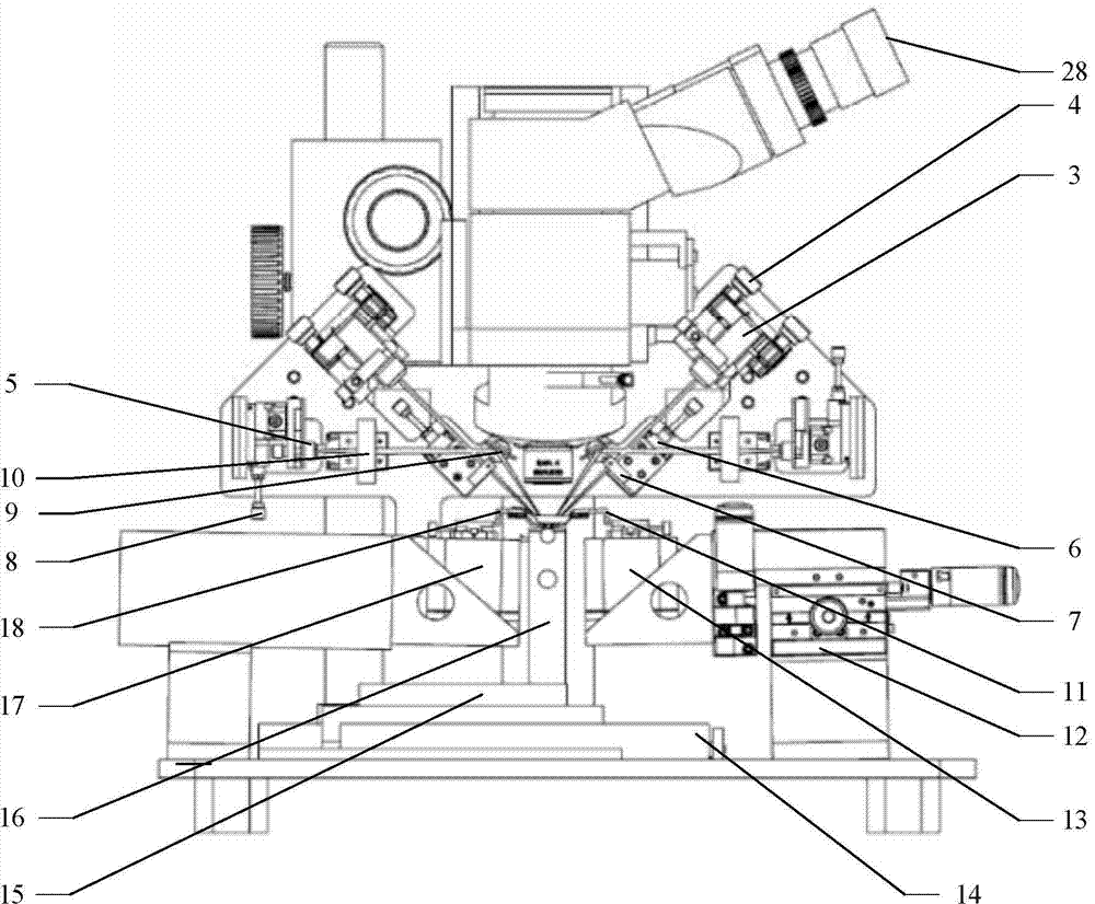
[0060] Specific implementation mode three: combination Figure 2 to Figure 4 Describe this embodiment. This embodiment is an imaging system based on the probe servo angle control module described in Embodiment 2. The imaging system includes an optical microscope 28, a host computer 20, a laser force measurement system I, a laser force measurement system II, The first probe hand 18, the second probe hand 11, XYZ micro-positioning stage II12, XYZ nano-positioning stage II13, XYZ micro-positioning stage III14, XY nano-positioning stage III15, sample stage 16 and YZ nano-positioning stage I17, two-way Probe controller 23, acquisition card 19, No. 1 piezoelectric controller 21, No. 2 piezoelectric controller 27, No. 3 piezoelectric controller 25, No. 1 switcher 22, No. 2 switcher 26 and the two have the same structure the probe holder 24;

[0061] The probe holder 24 includes a base 24-1 and a rotating arm 24-3, the rotating arm 24-3 is arranged on the base 24-1, and the rotating ...


PUM


Abstract

The invention discloses a probe servo angle control method and a control mode, an imaging system based on the control module, and an imaging method of the system, and relates to a technology of performing micro-nanostructure surface scanning imaging through an atomic force microscope, and aims to solve the problem that the traditional atomic force microscope cannot perform continuously controllable resolution three dimension scanning imaging on structure surfaces, such as an outward inclined surface with a large dip angle, a vertical side wall surface, an inward inclined surface and the like. By controlling the tip of a probe to be close to the surface of a sample in real time in a YZ plane along a vector forming an angle phi with an XZ surface, so as to perform scanning, and the phi can be automatically and dynamically adjusted according to scanned sample surface information, so that the uniform resolution scanning of surfaces with different angles is realized, and micro-nanostructure property detection and detection efficiency are convenient to improve, so that an important tool is provided for the super-large scale integrated circuit and ultra-large scale integrated circuit detection.

Description

technical field [0001] The invention relates to the technique of scanning and imaging the micro-nano structure surface by using an atomic force microscope (AFM). Background technique [0002] The traditional atomic force microscope (AFM) uses the Top-Down method to observe the surface topography of the sample. Its main function is to realize continuous scanning and imaging of the horizontal surface of the sample and the sloped surface with low inclination angle. For example, the patent with the publication number CN 104062466 A discloses An atomic force microscope-based micro-nano structure side wall surface imaging device and an imaging method for the device, the device and method can be used for such Figure 12 to Figure 15 The sidewall surfaces with different angles, such as the small-inclination-angle outer sloping surface, the large-inclination-angle outer sloping surface, the vertical sidewall surface, and the inner sloping surface, are scanned, but continuous and equal...

Claims


Application Information

Patent Timeline
Patent Type & Authority Applications(China)
IPC IPC(8): G01Q60/24G01Q60/38
Inventor 谢晖杨锋
Owner HARBIN INST OF TECH
Why Eureka
Try Eureka