JTAG signal generation method and generator

A signal generator and signal generation technology, applied in the direction of instruments, parts of electrical measuring instruments, measuring devices, etc., can solve problems such as error-prone and increase JTAG test workload, so as to reduce workload, improve efficiency, and improve appearance wrong effect

Inactive Publication Date: 2015-04-08
INSPUR BEIJING ELECTRONICS INFORMATION IND
View PDF5 Cites 1 Cited by
  • Summary
  • Abstract
  • Description
  • Claims
  • Application Information

AI Technical Summary

Problems solved by technology

[0008] The present invention provides a JTAG signal generation method and generator, which are used to solve the problems of error-prone and increased JTAG test workload caused by manually generating JTAG drive signals during JTAG testing in the prior art

Method used


Image

  • JTAG signal generation method and generator
  • JTAG signal generation method and generator
  • JTAG signal generation method and generator

Examples


Embodiment Construction

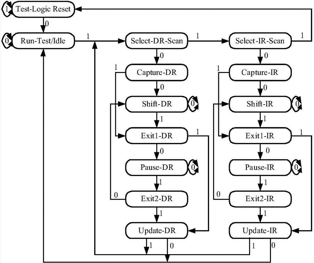
[0053] In order to enable those skilled in the art to better understand the technical solution of the present invention, a JTAG signal generation method and generator provided by an embodiment of the present invention will be described in detail below with reference to the accompanying drawings.

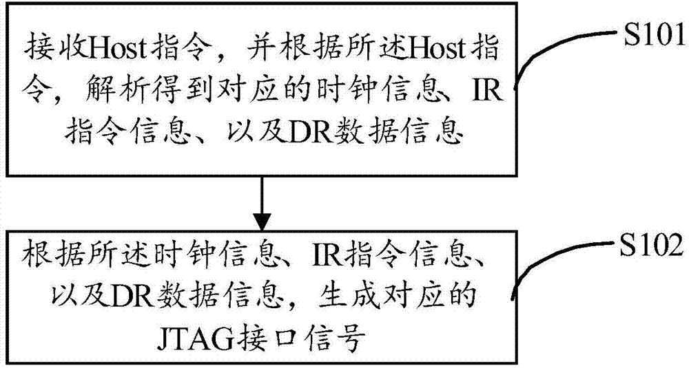
[0054] see figure 2 , a schematic flow chart of a method for generating a JTAG signal provided by an embodiment of the present invention, such as figure 2 As shown, the JTAG signal generation method that the embodiment of the present invention provides comprises:

[0055] Step S101, receiving a Host command, and analyzing and obtaining corresponding clock information, IR command information, and DR data information according to the Host command;

[0056] Step S102 , generating a corresponding JTAG driving signal according to the clock information, IR command information, and DR data information.

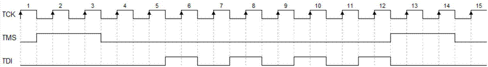
[0057] In the embodiment of the present invention, the Host instruction is a kind o...


PUM


Abstract

The invention provides a JTAG signal generation method and a generator; the method comprises the following steps: receiving Host instruction, analyzing to obtain the corresponding clock information according to the Host instruction, commanding the register IR command information, and the data register DR data information; generating the corresponding JTAG drive signal according to the clock information, IR command information and DR data information. The TDI, TMS drive signal with correct time order can be obtained after that the IR command information and DR data information are inputted according to the fixed HOST format. The loss of the time order or the bit loss of the inputted command and data caused by the complex TCK, TMS TDI can be avoided while the manual operation generation JTAG signal is imputed into the test environment, the workload for the JTAG test process can be reduced and the test work efficiency can be raised.

Description

technical field [0001] The invention relates to the field of chip design, in particular to a JTAG signal generation method and generator. Background technique [0002] As an interface standard of IEEE, JTAG (Joint Test Action Group) interface plays an important role in the testing, simulation and debugging of integrated circuits. Most of the existing advanced devices support the JTAG protocol, such as DSP, FPGA (FPGA Field Programmable Gate Array, Field Programmable Gate Array) and other devices. Through the built-in JTAG interface circuit in the chip, the boundary scan test of the chip can be realized. The JTAG interface circuit includes a TAP controller, an instruction register, and a data register. [0003] TAP (test port, test access port) controller is the core controller of the boundary scan test. According to the IEEE 1149.1 standard, the TAP controller has five driving signals, which are the test clock input signal TCK, the test mode selection signal TMS, the test...

Claims


Application Information

Patent Timeline
Patent Type & Authority Applications(China)
IPC IPC(8): G01R1/28
Inventor 徐强周恒钊
Owner INSPUR BEIJING ELECTRONICS INFORMATION IND
Why Eureka
Try Eureka