A chain link load aging device

A technology of aging device and chain link, applied in the direction of measuring device, instrument, measuring electricity, etc., can solve the problem of low efficiency of aging scheme of chain link, etc., and achieve the effect of improving aging efficiency

Active Publication Date: 2017-08-15
SHENZHEN INVT ELECTRIC
View PDF4 Cites 0 Cited by
  • Summary
  • Abstract
  • Description
  • Claims
  • Application Information

AI Technical Summary

Problems solved by technology

[0011] In view of this, the present application provides a chain link on-load aging device, which is used to solve the problem of low efficiency of the chain link aging scheme in the prior art

Method used


Image

  • A chain link load aging device
  • A chain link load aging device
  • A chain link load aging device

Examples


Embodiment Construction

[0066] Aiming at the problem of low aging efficiency caused by the aging scheme of chain links in the prior art, generally only one or two chain links can be aged at the same time, the application discloses a chain link on-load aging device.

[0067] The following will clearly and completely describe the technical solutions in the embodiments of the present invention with reference to the accompanying drawings in the embodiments of the present invention. Obviously, the described embodiments are only some, not all, embodiments of the present invention. Based on the embodiments of the present invention, all other embodiments obtained by persons of ordinary skill in the art without making creative efforts belong to the protection scope of the present invention.

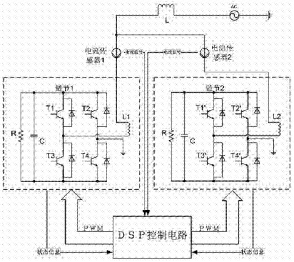
[0068] Figure 4 It is a structural diagram of the on-load aging device for chain links disclosed in the embodiment of the present application.

[0069] see Figure 4 , a chain link load aging device based on a triangu...


PUM


Abstract

The present application discloses a load aging device for chain links, which includes: first to sixth inductances connected to the first to third chain links and a control system, the first to sixth inductances are connected to the first to third inductances to form Triangular structure, the control system is used to output control signals to the first to third chain links, so that the output voltage of the first to third chain links contains the fundamental wave component with the same magnitude and phase as the grid voltage and the preset 3n times zero sequence The voltage component makes the output current of the first to third chain links contain 3n times of zero-sequence current components, and only flows inside the three chain links. A chain link is aged, thereby improving the aging efficiency.

Description

technical field [0001] The present application relates to the technical field of power electronics, and more specifically, relates to a chain link load aging device. Background technique [0002] The individual H-bridge inverters of static var generators with chain-link inverters are called chain links and are a key part of the static var generator. Chain link aging is a necessary step in the production process of cascaded static var generators. It can fully test the reliability of chain links under full pressure and full load to ensure the stability of the whole set of equipment after leaving the factory. The technology currently used is generally based on the energy exchange between the internal capacitance of the chain link and the external inductive load to achieve the purpose of outputting full load current, because the energy is exchanged between the internal capacitance and inductance of the chain link, and the aging device does not need to be powered from the power g...

Claims


Application Information

Patent Timeline
Patent Type & Authority Patents(China)
IPC IPC(8): G01R31/00
Inventor 凡念
Owner SHENZHEN INVT ELECTRIC
Why Eureka
Try Eureka