Optical cable transfer box

An optical cable junction box and box technology, applied in the direction of light guide, optics, optical components, etc., can solve the problems of box temperature rise, high temperature, fire, etc., to avoid short circuit phenomenon and achieve good fire extinguishing effect.

Active Publication Date: 2015-04-08
NINGBO LINGTONG TELECOM EQUIP
View PDF4 Cites 13 Cited by
  • Summary
  • Abstract
  • Description
  • Claims
  • Application Information

AI Technical Summary

Problems solved by technology

[0003] The current optical cable transfer box is mainly used for outdoor projects. Since the optical cable transfer box has an optical module card that will separate multiple optical fiber signal lines from the optical fiber circuit board to the optical fiber center backbone switch, there is heat during the transmission of optical fiber signals. And the optical cable transfer box is a relatively airtight box, the accumulation of heat will cause the temperature inside the box to rise, especially in the hot summer, the continuous high temperature will make the temperature inside the box very high, and then cause a fire, which will definitely damage the The transmission engineering of optical fiber signal causes serious consequences

Method used


Image

  • Optical cable transfer box
  • Optical cable transfer box
  • Optical cable transfer box

Examples


Embodiment Construction

[0019] The present invention will be further described in detail below in conjunction with the accompanying drawings and specific embodiments.

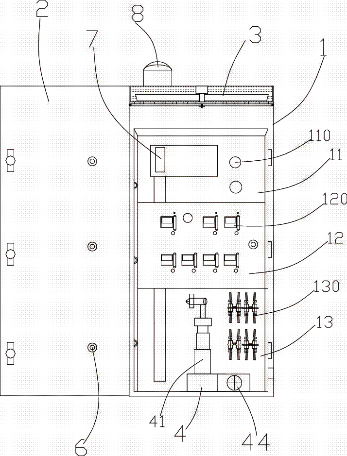
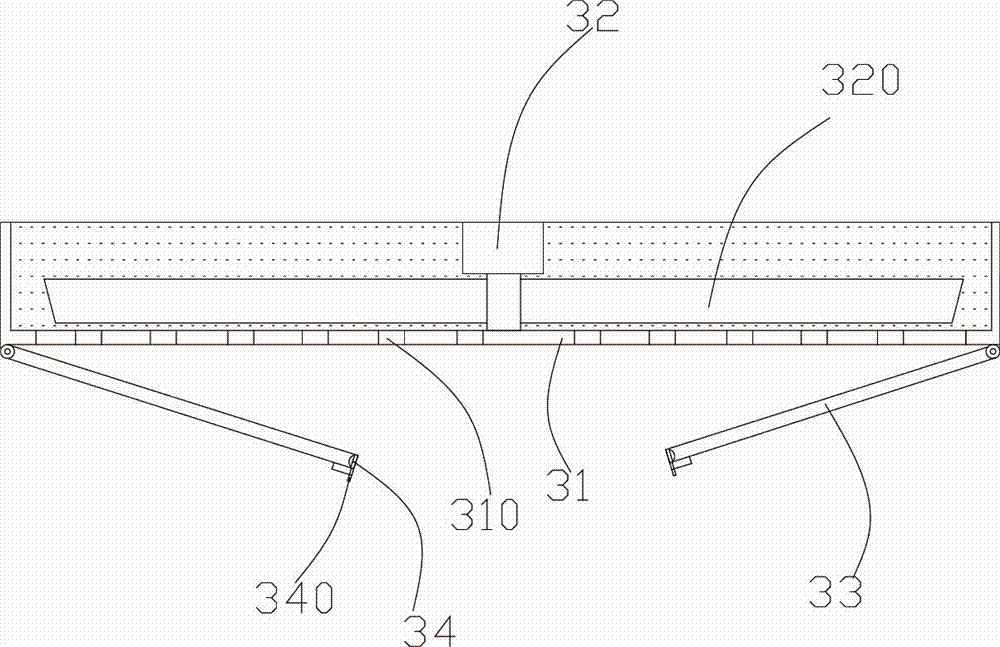
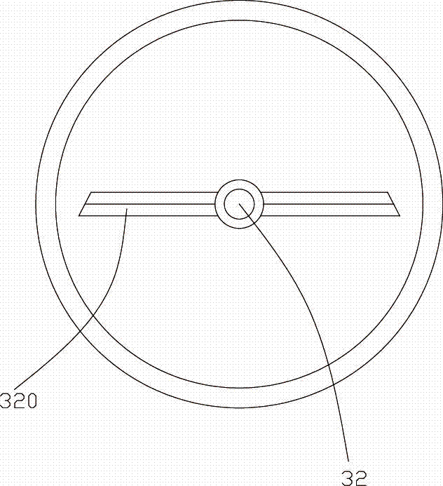
[0020] see Figure 1 to Figure 5 Shown is a specific embodiment of the optical cable junction box of the present invention. An optical cable transfer box, comprising an optical cable transfer box box body 1 and a box door 2 matched with the box body 1, and a public bin 11, a splitter bin 12 and a The wire routing bin 13, the public bin 11 is provided with a winding column 110, the optical splitter bin 12 is arranged with a splitter end 120, and an optical fiber connection socket 130 is arranged in the wire routing bin 13. The upper part of the box body 1 is provided with a sand falling mechanism 3, the sand falling mechanism 3 includes a partition 31, a through hole 310 is arranged on the partition 31, and a rotating shaft is arranged on the upper side of the partition 310. Motor 32, blades 320 are arranged on the output shaft of th...


PUM


Abstract

The invention discloses an optical cable transfer box, and belongs to the technical field of communication equipment. A sand falling mechanism is arranged in the upper part inside a box body. The sand falling mechanism comprises a partition plate, and a spatial area above the partition plate is filled with fine sands. Two symmetrical rotatable baffle plates are arranged at the lower side of the partition plate, and an electronic inductive switch is arranged at the front end of each baffle plate. A pneumatic cylinder is arranged in a wiring bin. A power output shaft of a stepping motor is connected with an air nozzle. The pneumatic cylinder is connected with an air pump. The air nozzle is sleeved with a thermal infrared sensing device. Compared with the prior art, by arranging the unique air jetting device and the sand falling mechanism in the optical cable transfer box, a fire occurring in the box body is extinguished first by high-pressure gas and then by the fine sands, the phenomenon of short circuit of an optical fiber line caused by fire extinguishing by water is avoided, the fire extinguishing effect is good, and the purpose of controlling fire and protecting equipment in the box body is achieved.

Description

technical field [0001] The invention belongs to the technical field of communication equipment, and in particular relates to an optical cable transfer box. Background technique [0002] The optical cable transfer box, or the optical cable distribution box, connects the outdoor optical cable signal lines to the optical fiber circuit board, separates multiple optical fiber signal lines from the optical fiber circuit board to the optical module card of the optical fiber center backbone switch, and realizes optical fiber Network access is mainly used for the new construction of 3G / 4G base stations in smart city fiber optic networks and FTTx broadband access projects, remote fiber optics, remote power supply, etc., all in outdoor environments and need to operate independently to further solve the problem of electromagnetic interference , saving electric energy, reducing emissions, low-carbon and environmentally friendly, can be applied to different installation methods such as o...

Claims


Application Information

Patent Timeline
Patent Type & Authority Applications(China)
IPC IPC(8): G02B6/44
CPCG02B6/4469
Inventor 邓奕丁高文雄林辉宣沈金标
Owner NINGBO LINGTONG TELECOM EQUIP
Why Eureka
Try Eureka